博客

主页

博客

  • Deburring: The Most Overlooked Manufacturing Process for Industrial Valves | GEKO Valve
    Deburring: The Most Overlooked Manufacturing Process for Industrial Valves | GEKO Valve
    Nov 18, 2026
    Deburring: The Most Overlooked Manufacturing Process for Industrial Valves During valve manufacturing, there is one peculiar process: almost every factory performs it, yet few treat it as a specialized technical discipline. Deburring is required after machining, tapping threads, and drilling holes. It must be completed for intersecting internal valve‑body holes, areas adjacent to sealing surfaces, and even parts that appear perfectly clean before assembly. In many production facilities, deburring has no dedicated workstation. Operators may handle it casually during machining, pass it to the next workflow, or perform rework only after burrs are discovered. Burrs are tiny defects. Unlike out‑of‑tolerance dimensions detectable via measurement, pressure leakage revealed by testing, or visible valve‑body cracking, burrs are hard to spot at a glance. However, seasoned valve manufacturers know countless field failures can ultimately be traced back to these minute metallic fragments. A single burr can scratch sealing faces, nick O‑rings during assembly, break loose as foreign debris inside valve cavities, alter local flow‑path geometry, create abnormal assembly torque on threaded connections. Some burrs remain undetected before shipment and only trigger failures after installation at end‑user sites. Although deburring seems like a simple finishing step, it directly determines valve functionality and long‑term reliability. Relying solely on operator experience for deburring easily creates hidden quality blind spots. At GEKO Valve, standardized deburring procedures are enforced across every production stage to eliminate avoidable in‑service failures caused by residual burrs. What Are Burrs and Why Are They Difficult to Remove? From a machining perspective, burrs are excess material protruding beyond nominal component contours, generated by plastic deformation or material tearing when cutting tools shear metal. Drilling, milling, turning, tapping, stamping, and forging all produce burrs or flash along parting lines. Burrs come in highly variable forms: some are thin metallic flakes, some are thick heavy flash, others feature razor‑sharp edges, while many hide deep inside bores and remain invisible to visual inspection. Valve manufacturing brings extra challenges. Valve bodies frequently feature multiple interconnected passages: main flow channels, side ports, stem bores, mounting holes, balance holes and pressure‑tap ports. Intersecting bore junctions readily generate internal burrs. The exterior of a valve body may look flawless, yet tiny hidden protrusions can persist inside. The real challenge of valve deburring is not just removing visible surface burrs, but reliably eliminating burrs from all functionally critical internal zones. GEKO Valve applies targeted deburring solutions for complex intersecting‑hole geometries on all cast and forged valve components. Why Are Valves So Vulnerable to Burr‑Related Damage? Valves are not ordinary mechanical structural parts. Minor burrs on a simple support bracket are merely cosmetic, yet internal valve burrs directly impair core operating functions. Sealing performance suffers the most. Spools, valve seats, gaskets and O‑rings operate with extremely precise clearances. Sharp burrs at bore openings can slice through sealing elements during assembly. Final assembly and hydrostatic pressure testing may pass without obvious defects, but seals will gradually leak after long‑term cyclic service. Post‑failure analysis often misattributes leakage to poor‑quality sealing material, while the root cause is unremoved burr damage during assembly. This represents a classic valve‑manufacturing failure mode: damage originates in one production step, yet symptoms only emerge in later assembly or field operation. For GEKO Valve, deburring management is tightly linked to sealing reliability rather than superficial cosmetic standards. How Micro Burrs Compromise Valve Assembly Performance Consider O‑ring installation inside a valve body. Under ideal conditions, the O‑ring slides evenly along smooth bore walls into its groove with uniform compression. If sharp burrs exist at bore edges, the elastomer may be scratched, nicked or sheared during fitting. In many cases, burrs do not fully sever O‑rings; they leave fine surface cuts. These micro‑scars may show no impact under low‑pressure ambient conditions. Once the valve enters service, fluctuating process pressure repeatedly compresses and relaxes the seal, small wounds propagate, and leakage eventually occurs. Many root‑cause investigations focus only on seal material, compression ratio and dimensional tolerances, ignoring whether seals sustained burr‑inflicted damage before installation. This risk grows with automated assembly lines. Human operators can feel abnormal resistance during manual fitting, but automatic assembly equipment lacks tactile feedback. Machinery will finish the pressing sequence without alarms, even when sealing components have already sustained hidden damage. How Burrs Disturb Valve Flow Characteristics Many engineers overlook this failure mechanism. For control valves, balancing valves and PICV products, flow‑path geometry directly governs fluid behaviour. Critical dimensions, orifice profiles, local contractions and expansions determine Kv‑value performance. Burrs at throttling sections modify effective flow‑passage area. Large‑bore main channels tolerate minor burrs, yet small orifices, throttle ports and balance holes are extremely sensitive. For a 2 mm‑diameter small bore, a 0.1 mm burr occupies a non‑negligible proportion of the cross‑section. Worse still, loosely attached burrs may detach during operation, migrating to block fine orifices or become wedged between plug and seat. For high‑precision modulating valves, deburring is not purely cosmetic finishing — it forms an essential part of flow‑path design. GEKO Valve implements dedicated deburring protocols for all trim components of control and regulating valves to preserve designed flow coefficients. Loose Detachable Burrs Pose the Greatest Risk Firmly‑attached burrs can at least be detected during inspection. Far more dangerous are poorly anchored micro‑burrs ready to break free. They may remain attached after machining, then dislodge during cleaning, assembly, transportation or field operation. Once dislodged, fragments travel randomly inside fluid loops. If debris enters tiny throttle ports, pressure‑feedback passages or close‑fitting trim assemblies, severe malfunctions follow. This risk is prominent for miniature proportional valves, pressure‑reducing valves, PICVs and pilot‑operated valves with intricate small‑size internal galleries. Many factories separate component deburring and part cleaning as independent processes. In reality, the two are closely connected: deburring eliminates debris at its source; cleaning removes residual contaminants. Even advanced washing procedures cannot fully compensate if burrs are not properly removed in earlier manufacturing phases. "Smooth‑to‑Touch" Is Not Sufficient Qualification for Valve Deburring A common‑field inspection practice relies on manual fingertip checks and visual observation to confirm "no burrs". This approach works for simple external components but proves inadequate for valves. Many critical zones including internal bores, intersecting holes, deep blind holes, thread roots and internal trim features cannot be reached or viewed directly by operators. Quantifiable acceptance criteria must be clearly defined: maximum allowable burr height (0.05 mm or 0.1 mm), permitted edge conditions, and differentiated specifications for different functional zones. Manufacturing quality cannot depend entirely on subjective human judgement. GEKO Valve establishes written deburring acceptance standards for every part drawing to achieve repeatable quality across mass production. Robust Deburring Starts at the Design Stage (DFM for Manufacturability) Numerous manufacturers assign full deburring responsibility solely to production teams after design finalisation. This creates major avoidable difficulties. Certain burr conditions cannot be easily fixed in post‑machining processing. Intersecting bores at sharp angles inherently generate difficult‑to‑remove burrs. Optimising bore locations, diameters, cutting directions and machining sequences in the design phase can drastically minimise burr formation. Some seal‑groove geometries make tool access extremely difficult, leaving deburring nearly impossible during mass production. Deep blind holes without consideration for tool access force manufacturers to rely on inconsistent manual labour. During product development, GEKO Valve’s engineering team evaluates key questions for each component: Where will burrs form? Can burr generation be minimised through geometry optimisation? Can deburring tools access critical zones? What reliable inspection methods verify completion? This follows DFM (Design for Manufacturability) principles. Excellent design delivers not just theoretically machinable parts, but components that can be stably, economically and repeatedly manufactured in high‑volume production. Summary Deburring is frequently underestimated within valve production workflows. Tiny residual burrs can trigger seal damage, assembly anomalies, distorted flow performance and loose foreign‑particle contamination, leading to premature field leakage or valve malfunction. Reliable deburring should not depend on operator experience alone. It requires clear drawing specifications, DFM‑optimised component geometry, standardized production workflows and proper inspection protocols. At GEKO Valve, strict deburring and cleanliness control throughout manufacturing safeguards long‑term reliability for industrial valves serving water treatment, chemical, power and oil‑gas projects worldwide. 9 Core SEO Keywords: industrial valve deburring, valve manufacturing quality control, valve burr removal, DFM for valve design, valve internal cleanliness, GEKO industrial valve, valve sealing reliability, control valve trim processing, intersecting bore deburring
    阅读更多
  • How Series-Parallel Dual Solenoid Control Improves ESD Valve Reliability | GEKO Valve
    How Series-Parallel Dual Solenoid Control Improves ESD Valve Reliability | GEKO Valve
    Nov 17, 2026
      How Series-Parallel Dual Solenoid Control Improves ESD Valve Reliability | GEKO Valve For gas turbine pressure regulating stations, the ESD (Emergency Shutdown Valve) acts as the critical safety barrier to cut off natural gas supply under abnormal conditions. Single-solenoid pneumatic control has long been a pain point, as a single solenoid failure can trigger unexpected valve closure and unit trip. GEKO Valve introduces a proven series-parallel dual two-position three-way solenoid configuration to boost the safety and availability of ESD valves for gas power plants.   What Is the Series-Parallel Dual Solenoid Control Loop for ESD Valves? The control loop adopts two 2-position 3-way solenoid valves arranged in a special series-parallel pneumatic layout.  Under normal steady operation, both Solenoid 1 and Solenoid 2 remain energized continuously. Port 2 connects to Port 1 while exhaust Port 3 is sealed. Compressed air flows through Solenoid 1 to supply air pressure to the pneumatic actuator of the GEKO ESD valve. Working Logic of the Redundant Solenoid Design 1. Single Solenoid Fault Condition If Solenoid 1 fails and de-energizes, its Port 1 switches to exhaust Port 3 and Port 2 is blocked. Thanks to the series-parallel layout, compressed air can still pass through Solenoid 2 and feed the ESD actuator. The GEKO ESD valve maintains its open position without losing air supply, avoiding nuisance shutdown. 2. Emergency Shutdown Condition To close the ESD valve for safety isolation, both solenoid valves must de-energize at the same time. Once both lose power, Port 2 of each solenoid is shut off, and Port 1 communicates with exhaust Port 3. The actuator air pressure vents out, and the GEKO fail-safe ESD valve closes immediately to isolate natural gas flow. With this design, the ESD valve will only trip when both solenoids malfunction, greatly lowering false trip risk. Power Supply Redundancy: The Second Layer of Safety Dual solenoid pneumatic redundancy alone is not enough. If both solenoids share one single power source, simultaneous power loss will still cause unintended ESD valve closure. GEKO recommends an independent redundant power architecture for this safety loop: Power from unit redundant UPS (or DC bus for DC solenoids) Two separate dual power switching modules Each switching module supplies power to one solenoid independently This separated power scheme eliminates common-cause power failure and matches the high safety requirement of gas turbine SIS loops. Maintenance & Operational Best Practices for GEKO ESD Valves Redundant hardware cannot replace routine management. GEKO Valve advises plant operators to build a complete solenoid asset management system: Maintain detailed solenoid registers, tracking service time, working environment and overhaul records Schedule periodic replacement for solenoids running for extended periods or in harsh high-humidity, dusty gas station environments Carry out regular partial stroke testing and full stroke testing on pneumatic ESD assemblies to detect hidden solenoid defects early Inspect air supply quality, filter condition and exhaust path during each outage window Why Choose GEKO ESD Valves for Gas Turbine Pressure Regulating Stations? GEKO emergency shutdown valves are engineered for natural gas, combined cycle power and process safety applications. Matched with optimized dual-solenoid redundant control solutions, GEKO ESD valves balance high safety integrity and operational availability. The fail-close pneumatic actuator package, certified sealing performance and robust construction make them a trusted choice for critical gas isolation duty on turbine regulating skids. Final Takeaway Series-parallel dual 3-way solenoid control is a practical and cost-effective upgrade to reduce nuisance trips of ESD valves. Combined with independent dual power supply and scheduled functional testing, this architecture delivers reliable safety protection for gas turbine sites. If you need technical support or quotation for GEKO ESD valves and solenoid control manifolds for your regulating station, contact our engineering team today.
    阅读更多
  • V‑Port Ball Valves: Why They Solve Jamming and Leakage for Particle‑Laden Media | GEKO Valve
    V‑Port Ball Valves: Why They Solve Jamming and Leakage for Particle‑Laden Media | GEKO Valve
    Nov 16, 2026
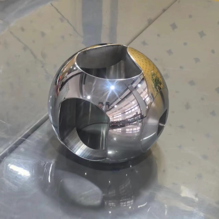
    V‑Port Ball Valves: Why They Solve Jamming and Leakage for Particle‑Laden Media Ball valves are not limited to simple on‑off service. One special variant, known as the V‑port ball valve, features a V‑notch cut on the ball core. It performs reliable shut‑off while delivering precise throttling and flow regulation capabilities. Many engineers encounter recurring jamming, leakage and stiff operation when applying standard O‑port ball valves for particle‑bearing, fibrous media in water treatment, mining and pulp‑and‑paper plants. In most cases, the root cause lies in incorrect valve type selection rather than product quality.  GEKO Valve’s V‑port ball valves are purpose‑built to handle these challenging abrasive process conditions. What Exactly Is a V‑Port Ball Valve? A conventional O‑port ball valve has a full‑bore circular opening on its ball, rotating 90° for complete open‑close action with only basic on‑off functionality.  By contrast, the ball of a GEKO V‑port ball valve is precision‑machined with a precise V‑shaped notch. As the ball rotates, the overlapping area between the V‑notch and valve seat changes following a predefined flow curve, enabling continuous, adjustable flow control. Simply put: a V‑port ball valve combines the tight shut‑off advantages of a ball valve with the modulating performance of a control valve. Most GEKO V‑port configurations deliver equal‑percentage flow characteristics; linear V‑notch profiles are also available upon request. For equal‑percentage characteristics, flow changes moderately at small openings and responds sensitively at larger openings, ideal for stable modulating processes. This differentiates V‑port designs fundamentally from standard O‑port ball valves with quick‑opening flow behaviour. V‑Port Ball Valve vs O‑Port Ball Valve: Key Differences The critical advantage comes from the sharp shear edge formed by the V‑notch. During rotation, this cutting edge shears fibres and breaks agglomerated particles off the seating surface, delivering the well‑known “self‑cleaning” effect. Standard O‑port ball valves lack this shear geometry and easily trap impurities between sealing faces. Comparison Item O‑Port Ball Valve GEKO V‑Port Ball Valve Primary Function Isolation & on‑off shut‑off On‑off isolation + flow modulation Flow Characteristic Quick‑opening Equal‑percentage / Linear (customizable notch) Anti‑clogging Performance Fair; particles easily become trapped Excellent; V‑notch provides shear self‑cleaning Frequent Modulating Service Not recommended Well‑suited; compatible with valve positioners Typical Media Clean fluids Particle‑laden, fibrous and viscous media How Does a GEKO V‑Port Ball Valve Prevent Clogging? Two common failure modes plague valves handling particle‑rich and viscous fluids: particles wedged between sealing surfaces causing leakage, and scale buildup leading to stiff actuation.  Throughout opening, closing and modulating cycles, the V‑notch continuously scrapes across the seat face to clear deposits and keep sealing surfaces clean. When paired with metal hard‑seated construction with hard‑alloy overlay welding or spraying on sealing faces, GEKO metal‑sealed V‑port ball valves withstand elevated temperature, high differential pressure and abrasive wear for extended service life. Metal‑sealed V‑port ball valves comply with GB/T 21385 standard specifications for metallic‑seated ball valves. Even so, V‑port ball valves are not universal solutions. They are not the optimal choice for ultra‑pure service, extreme high‑temperature conditions or very low‑differential‑pressure applications, where dedicated valve types should be selected instead. Main Industrial Applications for GEKO V‑Port Ball Valves Water & Wastewater Treatment: Return sludge, waste sludge, aeration branch lines and chemical dosing pipelines. Thanks to self‑cleaning performance, GEKO V‑port ball valves resist blockage better than globe valves or butterfly valves for suspension‑bearing water systems. Mining & Mineral Processing: Tailings slurry, concentrated ore slurry and heavily abrasive particle‑carrying media. Wear‑resistant GEKO V‑port ball valves with hard‑faced sealing surfaces are strongly preferred. Pulp & Paper Industry: Paper pulp, white liquor and black liquor with high fibre content and viscosity. The shear self‑cleaning geometry effectively prevents fibre entanglement on sealing interfaces. Hygienic Sanitary V‑Port Ball Valves: Food and pharmaceutical processes. GEKO sanitary V‑port ball valves are available in tri‑clamp or butt‑weld end connections with low‑Ra surface finish, supporting full CIP / SIP cleaning cycles for dairy, beverage and bio‑pharmaceutical metering and dosing pipelines. Lined V‑Port Ball Valves: Corrosive chemical and pharmaceutical service. Wetted surfaces lined with PFA or F46 fluoropolymer separate metallic components from aggressive media, combining accurate modulation with outstanding chemical resistance. Five Critical Points for V‑Port Ball Valve Selection Flow Characteristic: Choose equal‑percentage or linear V‑notch profiles according to your modulating requirements; GEKO supports custom V‑notch angle machining. Seat Material: Select metal hard‑seats for high‑temperature and abrasive‑wear duties; PTFE soft‑seats deliver tight shut‑off with limited temperature and chemical boundaries. Nominal Size & Differential Pressure: For large‑size and high‑delta‑pressure conditions, verify sufficient output torque from the actuator. Actuation Package: For modulating control, specify pneumatic or electric actuators complete with positioners accepting standard 4‑20 mA control signals, fully assembled and tested at GEKO factory. Media Corrosivity: Specify fluoropolymer‑lined or special alloy constructions for strongly corrosive process fluids. Relevant industry standards include GB/T 12237 for steel ball valves for petroleum‑petrochemical service, GB/T 4213 for pneumatic control valve actuation and testing, and GB/T 13927 for industrial valve pressure‑testing protocols. Quick Selection Reference Table Application Scenario Recommended GEKO V‑Port Ball Valve Type Key Reason for Selection Modulating service with fibrous or particle‑laden media General‑purpose V‑port ball valve V‑notch shear self‑cleaning; avoid O‑port ball valves for this duty High‑abrasion mine tailings and ore slurry Wear‑resistant hard‑faced V‑port ball valve Hard‑alloy overlay / sprayed sealing surfaces for anti‑abrasion performance Food‑pharmaceutical service requiring in‑place cleaning Sanitary hygienic V‑port ball valve Tri‑clamp / butt‑weld ends, compatible with CIP & SIP cleaning cycles Strongly corrosive chemical media Fluoropolymer‑lined V‑port ball valve PFA / F46 lining isolates valve body from aggressive process fluids Conclusion Integrating reliable shut‑off and accurate throttling within one unit, GEKO V‑port ball valves excel for “dirty, viscous and abrasive” working conditions across water‑wastewater, mining, pulp‑paper, food and pharmaceutical industries. If you face difficulties with specification, share detailed parameters including medium property, operating temperature and differential pressure with GEKO Valve’s engineering team for customised valve recommendations.
    阅读更多
  • GEKO Valve Shortlisted for LG Vietnam Semiconductor Substrate Project | High-Purity Semiconductor Fluid Control
    GEKO Valve Shortlisted for LG Vietnam Semiconductor Substrate Project | High-Purity Semiconductor Fluid Control
    Nov 16, 2026
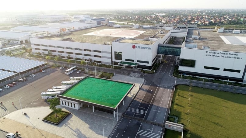
    GEKO secured vendor qualification for LG Innotek’s new $1 billion semiconductor substrate factory in Hai Phong, Vietnam, supplying high-purity ball valves & butterfly valves for UPW, chemical & utility piping systems.  Project Overview LG Innotek, a subsidiary of LG Group, invested approximately $1 billion to build its first overseas advanced semiconductor substrate manufacturing base in the DEEP C Industrial Zone, Hai Phong, Vietnam. The plant covers 330,000 ㎡ and focuses on FC-BGA, FC-CSP and RF-SiP substrates, serving AI chips, data center and 6G communication hardware. Construction kicked off in Q3 2026, with trial production scheduled in late 2027. Semiconductor substrate fabrication sets ultra-strict requirements for fluid control: zero particle shedding, low metal ion leaching, stable sealing against corrosive wet chemicals and consistent performance for ultrapure water (UPW) and plant utility loops. After a multi-round technical audit, sample testing and factory review, GEKO Valve successfully passed vendor qualification and was shortlisted for the project’s valve supply scope.   Project Challenges Ultra-high purity requirement: Wetted components must comply with SEMI F57 standard, controlled at ppt-level contamination to avoid wafer yield loss. Multi-medium working conditions: Mixed media including UPW, etching & cleaning chemicals, compressed dry air and cooling water. Long-term stable tight shut-off: Micro-leakage is unacceptable for clean process loops inside Class 100 cleanrooms. Localized after-sales support: LG’s Vietnam site required fast on-site technical service and inventory coordination in Southeast Asia. GEKO Customized Solution For this LG Vietnam semiconductor substrate project, GEKO proposed a matched valve package: High-purity 316L electropolished ball valves: Ra ≤0.25μm, PTFE sealing, for ultrapure water and clean process gas distribution PFA-lined butterfly valves: Excellent resistance to strong acid, alkali and oxidizing wet chemicals for chemical distribution skids Pneumatic actuated automated valves: With certified positioners and limit switches, integrated into the factory’s central DCS control system Full documentation traceability: Material test reports, EP surface inspection, particle & extractable test certificates, clean-room packaging GEKO leveraged its Southeast Asia service network to provide local technical support, pre-shipment clean packaging and commissioning guidance, meeting LG’s global semiconductor procurement specification. Why LG Selected GEKO Proven track record on high-tech, clean fluid projects across Vietnam and Singapore Strict quality control aligned with SEMI, ASME BPE international semiconductor standards Flexible material options: EP 316L, PFA lining, high-purity PTFE/Viton sealing for different process loops Complete local support channel in Vietnam, shortening lead time and response cycle Stable zero-leak performance, low particle release to protect substrate production yield Summary   Shortlisting for LG Innotek’s Vietnam semiconductor substrate project marks a key milestone for GEKO Valve in the global semiconductor fluid control market. GEKO will continue to optimize high-purity valve portfolio for wafer, substrate and packaging fabs, supporting semiconductor manufacturing expansion across Southeast Asia.
    阅读更多
  • 球阀终极指南及选购指南 | GEKO阀门
    球阀终极指南及选购指南 | GEKO阀门
    Oct 28, 2026
    球阀终极指南及选购指南 | GEKO阀门球阀是工业管道系统中应用最广泛的四分之一转流体控制装置之一。它们以运行速度快、密封可靠、维护成本低和结构紧凑而著称,在水处理、石油天然气、化工、发电等众多行业中发挥着关键的隔离和流量调节作用。本指南全面涵盖球阀基础知识、常见类型、关键规格和实用选型规则,帮助您根据工况选择合适的球阀。什么是球阀?球阀利用阀体内的空心多孔旋转球来控制流体流量。当球体孔与管道对齐时,阀门打开,介质通过。将球体旋转90度即可阻断通道,切断流体流动。大多数标准球阀设计用于实现严密关闭,而特殊设计的球阀则支持节流。GEKO阀门提供全系列球阀,旨在为工业项目提供可靠的密封性和长久的使用寿命。 常见球阀类型浮球阀 – 该球体并非由上下轴颈固定。流体压力将球体压向下游阀座,从而形成密封。适用于中低压应用,结构简单,经济高效。耳轴式球阀 球体由上下固定耳轴支撑。密封力并非完全依赖于管线压力。适用于高压、大尺寸、重载工业管道。顶部进入式球阀 – 无需将整个阀门从管道上拆卸下来,即可直接在现场进行维护。对于停机和拆卸成本高昂的关键管道而言,这是理想之选。侧入式(分体式)球阀 – 主体分为两个或多个部分,便于组装。广泛用于一般工业和水处理领域。全通径球阀与缩径球阀 全通径球阀的阀孔尺寸与管道内径相匹配,可最大限度地降低流动阻力和压降。缩径球阀的阀孔较小,成本更低,尺寸更紧凑,适用于流量损失不大的场合。衬里球阀 – 内衬 PFA、PTFE 或其他耐腐蚀材料,用于处理强酸、强碱和腐蚀性化学介质。球阀的主要组成部分阀体:主要承压壳体;常用材料包括 WCB、A105、304 不锈钢、316 不锈钢、双相钢和合金钢。球体:旋转闭合部件,有不锈钢、碳钢、硬面合金等材质可选,适用于磨损环境。座圈和密封件:PTFE、RPTFE、Viton、Devlon、金属座圈,适用于高温或防火要求。阀杆:将手柄或执行器产生的扭矩传递到球体;防爆阀杆设计是 GEKO Valve 球阀的标准安全功能。操作方式:手动操纵杆、齿轮箱、气动执行器、电动操作器(MOV)用于自动控制。主要工业应用石油和天然气:井口隔离、管道输送、炼油和储存终端化学工业:腐蚀性化学品输送、间歇式加工和反应器隔离水处理:原水、净水、污泥和废水管道发电厂:冷却水、蒸汽辅助系统和压缩空气管路食品饮料:卫生介质用卫生球阀氢能与清洁能源:用于氢气储存和运输的低泄漏球阀如何选择合适的球阀:分步检查清单1. 确认媒体属性确定流体类型:水、油、气、酸、碱、浆液或氢气。腐蚀性介质需要不锈钢或衬里结构。浆液介质需要硬面球和耐磨阀座,以避免磨损损坏。GEKO Valve 的技术团队可协助您针对难处理介质进行材料匹配。2. 工作压力和温度选择阀门压力等级(150、300、600、900 等)时,应与您的最大工作压力相匹配。检查温度限制:软密封球阀适用于中等温度环境,而金属密封球阀则适用于高温和防火环境。3. 阀门尺寸和流量要求如果低压降至关重要,请选择全通径接头。如果流量损失不是问题,则可以使用缩径接头。确认连接端类型:法兰、螺纹、对接焊或承插焊,以匹配您的管道。4. 操作类型手动杆:结构简单、成本低廉,适用于不频繁操作。齿轮驱动:适用于大型或高扭矩阀门气动执行器:快速启停,适用于自动控制系统电动执行器:非常适合远程控制和慢速切换5. 密封和安全要求软质阀座可在大多数一般工况下提供气密性密封。金属对金属阀座则适用于高温、防火、磨损或高循环工况。对于危险介质,可提供防火认证和低排放阀杆填料。6. 行业标准常用标准包括 API 6D、ASME B16.34、ISO 17292。请确认是否需要进行特殊测试,例如泄漏排放测试、水压测试和低温测试。球阀的优点和局限性优势90度快速开启和关闭,操作简便优异的紧密关闭性能结构简单,易损件少,使用寿命长适用于不同媒介的多种材料选择局限性标准软密封球阀不建议用于连续大幅度节流。高温可能会导致软质座椅材料老化。耳轴式和大型球阀的成本较高。最终选择提示选择球阀时,切勿仅根据公称尺寸和压力等级。务必评估介质腐蚀性、温度循环、动作频率和安全规范。如果您处理的是危险或高价值介质,请优先选择经过认证的低泄漏和防火安全型球阀。为确保长期可靠性,阀体、球体和阀座的材质应保持一致,避免混用不相容的材质。如果您对选型有任何疑问,请联系 GEKO Valve 获取技术支持。结论球阀是一种用途广泛、性能可靠的流体控制元件,但正确的选择直接决定着系统的安全性和使用寿命。本指南将带您了解球阀的核心类型、结构、应用场景和关键选择标准。明确介质、压力、温度、运行模式和标准要求后,您可以高效地为您的管道项目筛选出合适的球阀型号。目标关键词GEKO球阀、耳轴式球阀、浮动球阀、不锈钢球阀、PTFE阀座球阀、防火球阀、全通径球阀、工业球阀、低排放球阀
    阅读更多
  • 球阀材料指南:耐腐蚀性和耐久性 | GEKO阀门
    球阀材料指南:耐腐蚀性和耐久性 | GEKO阀门
    Oct 20, 2026
    球阀材料指南:耐腐蚀性和耐久性腐蚀和过早磨损是化工、海上作业、水处理以及油气管道系统中球阀失效的两大主要原因。选择合适的球阀材料直接决定其长期耐久性、密封完整性、安全性以及总体拥有成本。采用不相容合金或阀座材料制成的球阀可能出现点蚀、缝隙腐蚀、化学侵蚀或密封件劣化,导致泄漏排放、计划外停机以及昂贵的更换成本。本GEKO阀门指南按耐腐蚀性能、使用限制和适用工业应用对阀体、球体、衬里和阀座材料进行了分类,帮助工程师选择能够在腐蚀性介质中持久耐用的阀门。为什么球阀的耐腐蚀性和材料耐久性如此重要?与普通管道组件不同,球阀的湿润部件会与工艺流体(例如酸、碱、盐水、氯化物、溶剂和酸性介质)持续接触。即使是轻微的腐蚀也会导致旋转球卡死、密封表面损坏,并破坏压力控制。耐久性不仅指机械强度,还涵盖耐腐蚀性、温度稳定性、耐磨性和耐循环运行性。最佳材料的选择应在化学相容性、压力等级、温度范围和项目预算之间取得平衡,而不是一味追求最昂贵的超合金。 腐蚀性介质中常用的球阀阀体材料WCB碳钢WCB是通用球阀的标准铸造碳钢材质。它具有高机械强度和耐压性,但耐腐蚀性有限。碳钢适用于洁净油、蒸汽、天然气和非腐蚀性水。在腐蚀性环境中,WCB球阀依靠内部的PTFE或PFA衬里来隔离金属阀体与腐蚀性介质。如果没有衬里,碳钢在潮湿、酸性或富含氯化物的环境中会迅速生锈。304/316L不锈钢(CF8/CF3M)304不锈钢适用于低氯化物淡水、食品级流体和弱碱性溶液。316L不锈钢添加了钼元素,显著提高了其对氯离子、稀酸、废水和常见有机溶剂的耐受性。低碳316L不锈钢焊接后可避免晶间腐蚀,使其成为中等腐蚀环境下应用最广泛的不锈钢球阀。它仍然是水处理、制药和一般化工管线防腐蚀的首选材料。2205 和 2507 双相不锈钢双相不锈钢结合了奥氏体和铁素体两种组织,具有比316L更优异的耐氯化物腐蚀性能和更高的强度。2205双相不锈钢适用于盐水、微咸水和中等强度海水环境。2507超级双相不锈钢具有出色的抗点蚀和抗应力腐蚀开裂性能,适用于海水淡化、沿海化工厂和采出水管道等应用,而标准316L不锈钢在这些应用中会随着时间的推移而失效。 高性能合金:哈氏合金 C276、蒙乃尔合金 400、因科镍合金 625哈氏合金C276耐强氧化性酸、氯气、次氯酸盐和混合腐蚀性化学品,广泛应用于氯碱和精细化工工艺。蒙乃尔合金400对氢氟酸和海水具有优异的耐腐蚀性。因科镍合金625适用于高温腐蚀介质和热疲劳环境。这些镍基高温合金具有极佳的耐腐蚀性能,但材料成本更高,交货周期更长。PTFE/PFA衬里球阀衬里球阀采用碳钢或不锈钢阀体,并以连续的氟聚合物衬里覆盖所有接触介质的表面。PTFE 和 PFA 对大多数浓酸、浓碱和腐蚀性溶剂几乎无化学惰性。PFA 比 PTFE 具有更好的抗渗透性和更高的温度稳定性。对于中等压力范围内的强腐蚀性介质,衬里球阀是替代特种合金的一种经济有效的选择。球体和阀座材料:关键的密封界面阀体合金保护阀壳,而球体和阀座构成密封界面,控制泄漏并延长使用寿命。阀座材料失效是腐蚀性球阀最常见的耐久性问题之一。纯聚四氟乙烯: 具有通用的耐化学腐蚀性,几乎适用于所有腐蚀性介质。缺点:在持续压力下会产生冷流,长时间静置后可能会降低密封性能。RPTFE(增强型聚四氟乙烯): 填充玻璃、碳或石墨,可减少蠕变并提高耐磨性,同时保持广泛的化学兼容性。它是纯聚四氟乙烯最受欢迎的升级选择。窥视: 具有优异的耐腐蚀性、耐高温性和机械耐久性,适用于高循环和高压化学环境。氟橡胶/三元乙丙橡胶: 弹性体座圈适用于特定介质;氟橡胶适用于油类和碳氢化合物,三元乙丙橡胶适用于热水和弱酸。但两者都不耐强溶剂和浓酸。带司太立涂层的金属座: 适用于高温、磨蚀性浆料和防火环境的硬化金属密封表面。金属密封球阀依靠合金的选择来保证其耐腐蚀性,但无法像聚合物阀座那样实现完全密封。耐腐蚀性和耐久性关键选择清单在最终确定球阀材料之前,请核实以下应用参数:工艺流体的完整化学成分,包括痕量氯化物、固体和氧化剂工作温度和压力,以及异常和热循环条件流速和磨粒会导致侵蚀磨损关闭要求:气密性良好的软座或防火金属座外部环境:沿海盐雾、潮湿空气或地下埋葬维护通道和预期使用寿命目标通用申请匹配摘要淡水和弱化学介质 → 316L 不锈钢球阀,RPTFE 阀座。海水和盐水 → 2205/2507 双相不锈钢。浓酸和腐蚀性溶剂 → PFA 内衬球阀。氯气和混合氧化性化学品 → 哈氏合金 C276。高温磨蚀工艺 → 司太立合金硬面合金阀座,搭配相容的阀体合金。最后想说的话耐用、防腐蚀的球阀性能源于所有接触介质的部件均与工艺条件相匹配,而不仅仅是选择单一合金。GEKO阀门提供碳钢、不锈钢、双相钢、镍合金以及PFA/PTFE衬里等多种材质的球阀,并提供全系列的阀座和球体配件选择。合理的材料选择能够减少腐蚀引起的故障,并延长阀门在严苛的工业管道系统中的使用寿命。
    阅读更多
  • 球阀材料:工业应用中的优缺点 | GEKO阀门
    球阀材料:工业应用中的优缺点 | GEKO阀门
    Oct 14, 2026
    球阀材料:工业应用中的优缺点选择球阀材料需要在耐腐蚀性、耐温性、机械强度、成本和可加工性之间进行权衡。没有一种材料能够适用于所有工业流程。了解常用球阀阀体、球体和阀座材料的优缺点,有助于工艺工程师避免过早失效、意外泄漏以及在过于昂贵的合金上过度投入。本指南对比了GEKO工业球阀的常用材料,旨在帮助用户更快、更智能地进行阀门选型。WCB铸碳钢和A105锻造碳钢优点: A105锻造碳钢具有高抗拉强度、优异的高压高温性能、价格实惠、易于焊接和加工等优点。其晶粒结构更致密,抗冲击性优于铸造WCB钢,是关键高压管线、蒸汽和碳氢化合物应用的理想选择。缺点: 耐腐蚀性差。碳钢在潮湿、酸、氯化物和大多数腐蚀性化学品的侵蚀下会迅速生锈。不适用于饮用水、盐水或持续潮湿腐蚀性环境。在低温下,冲击性能会急剧下降。SS304 / CF8 不锈钢优点: 对清水和弱碱性介质具有良好的耐腐蚀性,在中等温度下耐氧化,易于消毒,是一种经济实惠的不锈钢选择。广泛应用于卫生、食品饮料、市政供水和一般户外管道系统。缺点: 在含氯化物环境(例如海水和盐水)中易发生点蚀。耐强酸性能差。不建议用于高盐度或苛刻的化学工艺。SS316 / 316L (CF8M / CF3M) 不锈钢优点: 添加钼元素可显著提高耐氯化物和弱酸性能。316L低碳钢焊接后可有效抵抗晶间腐蚀。用途广泛,适用于化工、食品生产、海水淡化预处理和海洋非海水回路。它是腐蚀性工业应用中最受欢迎的不锈钢。缺点: 仍然容易受到浓氯化物、高温盐水和强还原性酸的腐蚀。成本高于304不锈钢,且在严苛的腐蚀环境下无法与双相不锈钢或镍基合金相媲美。2205双相不锈钢优点: 结合了奥氏体和铁素体组织,具有高机械强度和优异的抗氯化物点蚀性能。在微咸水、盐水和低至中等酸性条件下,性能优于316不锈钢。对于海水相关应用,比哈氏合金和其他镍基合金更经济。缺点: 高温工作范围有限;过热时耐腐蚀性降低。延展性不如奥氏体不锈钢,加工难度更大。不适用于强还原性酸。PFA/PTFE衬里材料优点: 几乎对所有强酸、强碱和腐蚀性溶剂都具有化学惰性。金属外壳提供结构强度,而氟聚合物内衬则隔离腐蚀性介质。非常适合在标准金属容易快速腐蚀的严苛化学加工环境中使用。缺点: 衬里容易被磨蚀性浆料划伤。不适用于高温蒸汽。其耐温和耐压等级低于实心金属阀门,而且衬里阀门比碳钢阀门更重、更贵。哈氏合金C276、合金20和蒙乃尔镍合金优点: 对氧化性酸、酸性气体(硫化氢)、氯气和多种腐蚀性化学品具有卓越的耐受性。对应力腐蚀开裂和局部点蚀具有优异的抵抗力。这些特种合金适用于316不锈钢和双相不锈钢无法胜任的关键高风险工艺。缺点: 镍合金的原材料和加工成本非常高,交货周期也很长。镍合金仅适用于极端腐蚀性环境,因此不适用于普通的水、油或蒸汽管道。常用座圈和密封件材料:聚四氟乙烯 (PTFE)、氟橡胶 (FKM)、金属、聚醚醚酮 (PEEK)。聚四氟乙烯: 优点——化学性质稳定,密封严实;缺点——容易出现冷流,高​​温范围有限。FKM(氟橡胶): 优点——耐油、耐燃料和耐碳氢化合物;缺点——与酮类和某些强酸不相容。金属座椅: 优点——适用于高温、磨蚀性介质和频繁循环;缺点——密封性差,扭矩要求较高。窥视: 优点——优异的耐磨性和耐高温性;缺点——价格昂贵,供应有限。快速比较指南碳钢最适合用于非腐蚀性高温蒸汽和油类介质。304不锈钢适用于清洁、低氯化物水和卫生轻型应用。316不锈钢在性能和预算之间取得平衡,适用于一般腐蚀性应用。2205双相不锈钢是盐水和高氯化物水的首选材料。衬里阀门可处理腐蚀性化学品,而镍合金则专用于极端腐蚀性工艺条件。GEKO阀门公司的结语材料选择绝不应仅以成本为依据。廉价的阀门如果过早失效,将导致更高的停机时间和维护成本。请将您的介质、温度、压力和化学浓度信息告知GEKO的工程团队,以便我们为您选择最适合您工业应用的球阀材料。
    阅读更多
  • 哪种球阀材料最适合您的应用? | GEKO阀门
    哪种球阀材料最适合您的应用? | GEKO阀门
    Oct 14, 2026
    哪种球阀材料最适合您的应用?选择合适的球阀材料是确保工艺可靠性的关键决策之一。即使是设计精良的球阀,如果阀体、球体和阀座的材料与您的流体、温度、压力和化学环境不兼容,也会过早失效。从WCB碳钢和不锈钢到双相钢、PFA衬里和特种合金,球阀材料种类繁多,工程师和采购团队需要一个清晰的框架,以便根据具体的工况选择合适的材料。本指南详细介绍了常见的球阀材料、它们的优势、局限性和理想应用场景,帮助您为您的系统选择合适的GEKO球阀。决定球阀材料的核心因素在比较材料之前,请确认四个关键工艺参数。流体介质和化学浓度决定腐蚀风险。工作温度影响材料的韧性、抗蠕变性和密封性能。工作压力决定壁厚和机械强度要求。其他因素包括氯化物含量、磨蚀性颗粒、循环切换频率以及食品或制药行业的卫生要求。  WCB碳钢/A105锻钢球阀WCB铸碳钢和A105锻造碳钢是经济高效、强度高的无腐蚀性介质管道选择。它们在高温下性能可靠,适用于发电厂、热力系统和一般油气行业的蒸汽、压缩空气、燃油和天然气管道。碳钢在-29°C至约425°C的温度范围内均可良好工作,但暴露于水、酸或富含氯化物的流体中会迅速生锈。因此,不建议将其用于潮湿腐蚀性环境、饮用水或化工管道。SS304(CF8)不锈钢球阀SS304不锈钢是水处理、清水、弱碱性流体和一般户外管道应用的标准耐腐蚀球阀材料。它具有良好的抗氧化性和优异的低温韧性,因此广泛应用于一般工业和卫生领域。SS304适用于低氯化物水,但在盐水、浓盐水和高氯化物介质中会逐渐出现点蚀。SS316 / 316L (CF8M / CF3M) 不锈钢球阀SS316不锈钢含有钼元素,显著提高了其耐氯化物、弱酸和多种化学溶剂的性能。它是化工厂、海水淡化预处理、食品饮料加工以及非海水海洋回路中最常用的不锈钢牌号。316L低碳型不锈钢可减少焊接后的晶间腐蚀,是长期连续化学应用的理想选择。对于大多数一般腐蚀性工业应用而言,SS316是SS304的默认升级选择。2205双相不锈钢球阀2205双相不锈钢兼具高机械强度和优异的抗氯化物点蚀性能。在微咸水、海水、盐水和中等酸性环境中,其性能优于316不锈钢。双相球阀广泛应用于海水淡化、海上辅助管线和矿井水系统。它在强度和耐腐蚀性之间取得了平衡,无需使用昂贵的镍合金,但其高温极限比许多其他不锈钢牌号要窄。PFA/PTFE衬里球阀PFA 和 PTFE 衬里球阀采用碳钢或不锈钢压力壳体,内衬氟聚合物,与流体接触。该衬里对大多数强酸、强碱和腐蚀性溶剂具有化学惰性。这些衬里球阀是金属合金无法承受的严苛化学工艺的首选。它们不适用于高温蒸汽或可能刮伤衬里表面的磨蚀性浆料。特种合金球阀:哈氏合金、20号合金、蒙乃尔合金对于浓酸、酸性气体、硫化氢和氧化性化学品等极端腐蚀性环境,GEKO 提供由哈氏合金 C276、合金 20 和蒙乃尔合金制成的球阀。这些特殊合金能够抵抗局部腐蚀和应力开裂,即使在 316 不锈钢和双相不锈钢容易受到腐蚀的环境中也能保持优异的性能。它们材料成本较高,仅适用于关键化工、氢气和高风险工艺应用。座椅和密封件材料匹配(不仅限于主体材料)单凭阀体材料无法保证可靠的关闭。阀座材料也必须与工艺条件相匹配。聚四氟乙烯(PTFE)阀座可为大多数清洁流体在中等温度范围内提供气密性隔离。氟橡胶(FKM,也称Viton)适用于油类和碳氢化合物。金属阀座适用于高温、磨蚀性介质和频繁循环工况。聚醚醚酮(PEEK)阀座具有出色的耐磨性,可满足严苛的循环工况要求。即使阀体材料选择正确,阀座材料与介质不匹配也是造成泄漏的常见原因。快速应用参考蒸汽、油、压缩空气:WCB/A105碳钢清水,食品级温和液体:SS304适用于一般化学品、低氯化物腐蚀性环境:SS316 / 316L海水、盐水、高氯化物水:2205双相不锈钢强酸和腐蚀性化学品:PFA衬里球阀酸性气体、高浓度腐蚀性介质:哈氏合金或镍合金GEKO阀门公司的最终建议最佳球阀材料应兼顾耐腐蚀性、耐温耐压等级、使用寿命和预算。过度选用特殊合金会增加不必要的成本,而选用不足则会导致计划外停机和安全隐患。如果您不确定哪种材料适合您的工艺流体,请将您的介质、温度、压力和浓度数据提供给GEKO的工程团队,以便他们为您提供经过验证的材料推荐。
    阅读更多
  • 蝶阀如何开启和关闭?完整操作指南 | GEKO阀门
    蝶阀如何开启和关闭?完整操作指南 | GEKO阀门
    Oct 09, 2026
    蝶阀如何开启和关闭?完整操作指南蝶阀是工业和市政管道系统中应用最广泛的四分之一转流量控制装置。许多工程师和采购专家选择使用蝶阀。 工业蝶阀 蝶阀因其结构紧凑、成本低廉而备受青睐,但鲜有人真正了解其完整的开启和关闭机械过程。与直线行程闸阀和截止阀不同,蝶阀依靠精确的旋转运动来改变管道的流态。本文将清晰阐述蝶阀的开启和关闭工作原理、不同阀门设计的机械逻辑、驱动方式以及密封配合原理。1. 蝶阀的基本开启和关闭原理蝶阀的整个开启和关闭动作是通过一个 90度四分之一圈旋转其核心运动部件包括阀杆和内部蝶形阀瓣。阀杆接收来自手动或自动执行器的扭矩,驱动阀瓣在管道内水平旋转,实现全开、全关和中间节流状态。闭合过程(90° → 0°):阀瓣沿垂直于流体流动方向的方向逐渐旋转,不断缩小流道。当旋转至0度时,阀瓣完全压紧阀座,堵塞管道,实现严密关闭。开启过程(0° → 90°)圆盘沿流体流动方向平行旋转,逐渐扩大流通面积。旋转至 90 度时,圆盘完全打开,最大限度降低流动阻力,实现最大流体通过。这种简单的旋转操作正是其工作原理所在。 蝶阀 和 耳形蝶阀 非常适合大口径管道。2. 完整的机械作用过程 开合循环遵循固定的机械传动链,确保运行准确稳定:首先,操作装置(操纵杆、齿轮箱、气动或电动执行器)输出旋转扭矩。该扭矩通过驱动轴传递至中央阀杆。一体式阀杆和阀瓣结构同步旋转,无空转。运动过程中,阀瓣逐渐与密封座分离或压缩。最后,机械限位装置锁定角度,完成开启或关闭定位。3. 不同阀门结构的开启和关闭逻辑同心蝶阀和偏心蝶阀在开启和关闭摩擦力方面存在明显差异,这直接影响使用寿命和运行稳定性:3.1 同心蝶阀操作同心蝶阀的阀杆、阀瓣和管道中心相互重叠。在每次开启和关闭行程中,阀瓣始终与阀座保持接触和摩擦。该阀门操作简便、成本低廉,适用于常规水处理和暖通空调管道的低频切换。3.2 三偏心蝶阀零摩擦运行三偏心蝶阀 采用三维错位结构。开启过程中,阀瓣瞬间与阀座无摩擦分离。关闭过程中,阀瓣仅在最终锁定位置与阀座接触。这种零摩擦的开启和关闭机构大大降低了阀座的磨损,使得这种阀座具有以下特点: 重型蝶阀 适用于高温、高压、频繁切换的工业管道。4. 开门和关门过程中的密封协调不同的密封类型对应不同的开启和关闭机械特性:4.1 软密封蝶阀软密封蝶阀 采用 EPDM 或 NBR 材质的阀座依靠弹性压缩实现完全关闭时的零泄漏。关闭时,阀瓣轻柔地挤压弹性阀座,填补微小缝隙。开启时,弹性阀座自动复位。这种灵活的密封开启和关闭方式确保了对清洁水和气体介质的完全密封。4.2 金属密封蝶阀金属密封蝶阀 采用精密金属对金属配合。开合过程实现了刚性机械配合与分离。具有高耐磨性和耐温性,即使在高温蒸汽、磨蚀性浆料等恶劣工作条件下也能保持稳定的开关性能。5. 自动蝶阀的开启和关闭方式现代工业管道采用自动蝶阀实现智能化的启闭控制:气动蝶阀该阀门由压缩空气驱动,可在数秒内完成快速的开启和关闭动作。它具有防爆优势,广泛应用于化工和石油化工管道切换。电动蝶阀该装置采用电动执行器驱动,具有速度稳定、角度定位精确和远程信号控制等特点。它支持延时开启/关闭和中间定位功能,适用于智能管道系统。手动蝶阀:通过杠杆或齿轮手轮操作,可实现现场手动开启和关闭,经济方便,适用于低频操作场景。6. 常见的开门和关门故障及原因阀门卡住:由沉积物堆积、阀座老化或执行器扭矩不足引起关闭不完全和泄漏:盘片偏移、座圈磨损或异物堵塞密封表面缓慢的开合速度气动气压不足或电动执行器参数偏差7. GEKO阀门精准的开启和关闭性能所有GEKO蝶阀均采用优化的旋转运动结构,确保灵活、平稳、精准的开启和关闭动作。我们全系列产品,包括对夹式、凸耳式、软密封式、金属密封式和三偏心蝶阀,均可实现零摩擦切换、稳定密封和长使用寿命。自动化 调节蝶阀 支持任意角度的开启和关闭,满足现代工业管道系统的隔离和节流控制要求。
    阅读更多
  • 蝶阀在管道系统中扮演什么角色? | GEKO阀门
    蝶阀在管道系统中扮演什么角色? | GEKO阀门
    Oct 09, 2026
    蝶阀在管道系统中起什么作用?工业和市政管道网络在庞大的设施中输送液体、气体和浆料,需要可靠的流量控制硬件来确保运行的安全性和可预测性。作为一种常用的四分之一转阀,蝶阀在管道系统中发挥着多种核心功能。其结构紧凑、阀体轻巧且操作模式灵活,使其成为从大型供水干管到化工生产线等众多管道设计的首选。本文将详细介绍蝶阀在管道系统中发挥的关键作用及其优势所在。1. 管道维护和紧急关闭的流体隔离蝶阀的主要功能之一是正向隔离。当管道段、泵或下游设备需要检查或维修时,操作人员会关闭蝶阀以完全切断流体流动。在管道过压或设备故障等紧急情况下,蝶阀可以快速关闭管线,防止泄漏和系统损坏。凸耳式和法兰式蝶阀常用于隔离作业,其PTFE或EPDM阀座可提供严密的关闭性能。2. 流量节流和流量调节除了简单的开关功能外,蝶阀还广泛用于流量节流。通过旋转阀瓣至部分开启位置,阀门可以调节横截面过流面积,从而控制管道内流体的流量和流速。此功能有助于稳定压力,并维持诸如水分配、暖通空调循环和化学品输送等工艺流程的稳定流量。需要注意的是,精确节流需要选择合适的材料,以避免高速介质对阀瓣造成侵蚀。3. 压力控制和浪涌抑制蝶阀有助于管理管道压力。其缓慢开启或关闭可以缓解泵启动和停止时产生的压力峰值。在大直径管道系统中,慢速蝶阀有助于减少可能损坏管道配件和仪表的“水锤”效应。在现代管道网络中,蝶阀通常与气动或电动执行器配合使用,以实现自动压力调节。 4. 分流和流向切换在多分支管道系统中,多组蝶阀协同工作,将流体分流到不同的分支。例如,在水处理厂中,它们用于切换不同滤池之间的流量;在区域供热系统中,它们用于将热水分配到不同的建筑区域。这样,在重新分配工艺介质时,就无需关闭整个管道系统。5. 防止回流(辅助功能)虽然蝶阀并非专用止回阀,但在某些低风险管道应用中,正确配置的蝶阀可以帮助限制不必要的逆流。对于关键的回流保护,蝶阀通常与专用止回阀组合使用,作为完整的管道安全组件的一部分。蝶阀在管道网络中的主要优势节省空间的设计:比闸阀或截止阀薄得多,非常适合空间有限的管架安装。重量轻:降低管道支架的结构荷载,从而降低项目总成本。快速四分之一圈旋转操作:可选手动操纵杆、齿轮、气动或电动驱动方式尺寸范围广:适用于小型工艺管线和大直径主管道。耐腐蚀选项:可提供用于腐蚀性化学介质的衬里蝶阀根据管道角色选择合适的管道连接方式对于水和废水隔离应用,请选择弹性密封蝶阀。对于腐蚀性流体,建议使用聚四氟乙烯(PTFE)衬里的蝶阀。如果需要自动控制,请指定气动或电动执行器,以便与工厂控制系统集成。请确认压力等级、法兰标准和阀座材料是否与管道介质和工作温度相匹配。概括在管道系统中,蝶阀主要发挥五大作用:流体隔离、流量节流、压力管理、流量分流和辅助回流控制。凭借其紧凑的尺寸和多样化的驱动方式,蝶阀可在水、化工、电力和暖通空调管道网络中提供可靠的流量控制。选择合适的蝶阀设计可确保管道长期稳定运行,并减少计划外停机时间。
    阅读更多
  • 水处理厂中的蝶阀是如何工作的? | GEKO阀门
    水处理厂中的蝶阀是如何工作的? | GEKO阀门
    Oct 09, 2026
    水处理厂中的蝶阀是如何工作的?水处理厂依靠稳定、经济高效的流量控制设备来管理原水取水、化学药剂加药、过滤、消毒和废水排放。蝶阀因其结构紧凑、操作快捷(只需四分之一圈)、重量轻且价格实惠,在水处理的各个阶段都得到了广泛应用。与笨重的闸阀相比,蝶阀可以节省安装空间,并降低水厂常见大口径管道的结构负荷。本文将阐述蝶阀在关键水处理工艺中的工作原理及其实际操作优势。水处理服务的核心工作原理蝶阀使用安装在中心轴上的圆形阀瓣。当阀门旋转90度时,阀瓣会平行或垂直于流体流动方向旋转。在全开位置,水流阻力极小;在关闭位置,阀瓣紧贴阀座,切断水流。在全开和全关之间,部分旋转可以实现节流,从而控制水流量。大多数水处理蝶阀采用弹性橡胶阀座,例如三元乙丙橡胶(EPDM),可确保清洁介质和废水介质的密封性。 水处理厂内部的典型应用1. 原水取水口及泵站蝶阀安装在进水管路和泵出口处,用于在泵维护期间隔离管道。它们可以快速切断来自河流、湖泊或水库的原水,从而保护下游过滤装置。由于大型对夹式或凸耳式蝶阀易于安装在管道法兰之间,因此通常选用此类蝶阀。2. 混凝池、絮凝池和沉淀池在沉淀池中,蝶阀用于调节处理室之间的水流。操作人员通过调节阀瓣角度来平衡水流速度,从而促进絮凝体稳定形成和固体沉淀。手动或齿轮式蝶阀广泛应用于频繁开关和中等流量调节作业。3. 过滤系统砂滤器和活性炭滤池组采用蝶阀来切换过滤和反冲洗循环。这些阀门隔离各个过滤单元,因此单个滤池可以进行反冲洗而无需关闭整条处理线。EPDM阀座可耐受定期冲洗和含颗粒水的磨损。4. 消毒和化学加药管线对于氯气、次氯酸钠或 pH 值调节化学品管道,衬里蝶阀可防止化学添加剂造成的腐蚀。它们为计量撬装设备和混合室的维护提供了可靠的隔离。5. 污水排放和废水出口处理后的水排放前,蝶阀控制排放流量并起到紧急切断装置的作用。管线末端通常选用凸耳式蝶阀,以便在需要时进行盲法兰隔离。水处理蝶阀选型的关键考虑因素座圈材质:EPDM是清洁水的标准材质;对于含有悬浮固体的废水,应选择更耐磨的座圈材质。主体材料:球墨铸铁是水利工程中主流且经济实惠的选择。驱动方式:手动齿轮箱用于偶尔操作;气动或电动执行器用于自动化工厂SCADA控制。压力等级:与管道工作压力以及泵启动和停止时的冲击压力相匹配阀门类型:用于紧凑型安装的对夹式蝶阀;用于终端管路的凸耳式蝶阀水处理厂中蝶阀的优势其轻巧的设计降低了管道支撑成本,而快速的四分之一圈旋转操作则加快了紧急停机速度。它们易于实现自动化,适用于现代智能水厂,并且比许多其他阀门所需的维护更少。主要的局限性在于,标准的弹性密封蝶阀不适用于高压蒸汽或高磨蚀性重浆,这些情况需要其他阀门解决方案。概括从原水取水、过滤、化学处理到最终排放,蝶阀在整个水处理流程中都发挥着多功能流量隔离和节流的作用。尺寸合适的蝶阀,搭配合适的阀座和阀体材料,有助于水厂保持稳定运行,减少停机时间,并降低整体项目和维护成本。
    阅读更多
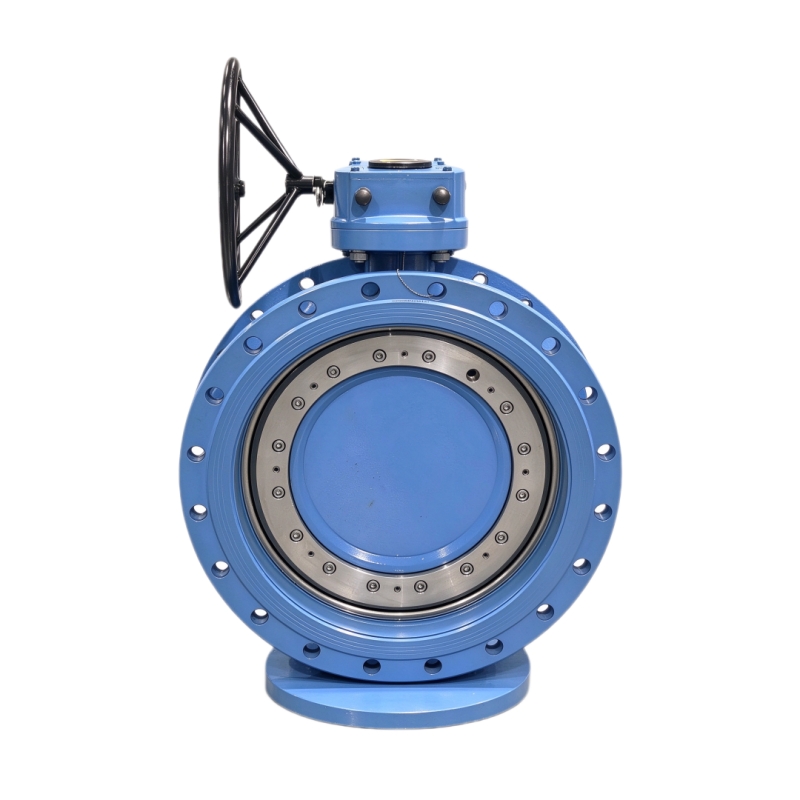
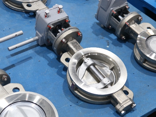
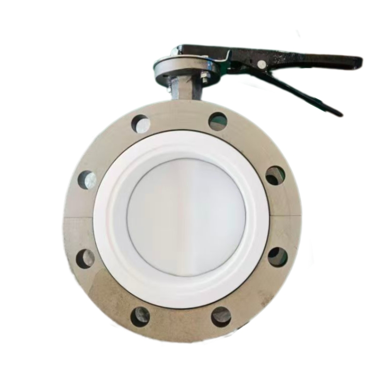
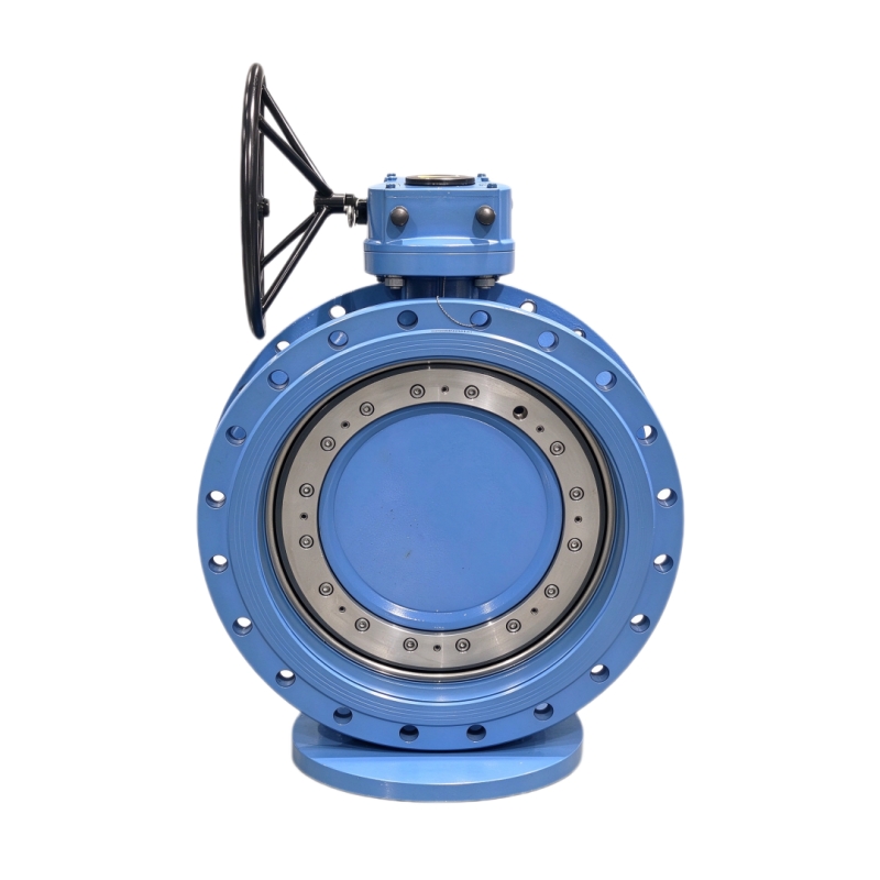
  • 什么是蝶阀?它的主要部件有哪些? | GEKO阀门
    什么是蝶阀?它的主要部件有哪些? | GEKO阀门
    Sep 29, 2026
     什么是蝶阀?它的主要组成部分是什么?蝶阀是一种常用的四分之一圈流量控制装置,广泛应用于市政和工业管道系统中,用于调节、节流或完全切断流体流量。其纤薄轻巧的设计使其比球阀或闸阀更节省空间,尤其适用于大直径管道。许多新用户和工厂工程师都希望了解蝶阀的工作原理以及各个内部部件如何协同工作以实现可靠的性能。本文将详细介绍蝶阀的定义、核心功能和所有关键部件。 蝶阀. 蝶阀的定义和核心功能最简单的蝶阀是通过旋转管道内的圆形阀瓣来控制流体。旋转90度即可将阀门在全开和全关位置之间切换。它还可以保持在中间角度,以调节流量。 晶片式蝶阀 和 耳形蝶阀 是两种最常见的车身样式,而偏置式设计则有 三偏心蝶阀 蝶阀可应对严苛的高温高压应用。它适用于水、空气、气体以及多种化学介质,广泛应用于水处理、暖通空调、电力和化工行业。蝶阀的关键部件1. 阀体阀体构成主要的承压壳体,并与管道连接。对夹式阀体安装在两个管道法兰之间,无需螺栓凸耳。凸耳式阀体则带有内置螺纹凸耳,用于牢固地固定法兰。重型 金属密封蝶阀 采用铸铁、球墨铸铁、不锈钢或合金钢机身,以承受恶劣的工作环境。2. 蝴蝶盘阀瓣是阀体内的圆形板,用于阻挡或允许流体通过。它随阀杆一起旋转。阀瓣的形状直接影响流体阻力。同心阀使用平面阀瓣;双偏心阀和三偏心阀使用弧形阀瓣,以减少旋转过程中阀座的摩擦。对于腐蚀性介质,阀瓣会进行涂层处理或采用不锈钢材质,以延长使用寿命。3. 气门杆阀杆是一根穿过阀体并与阀瓣牢固连接的轴。它将来自执行器或手轮的扭矩传递到阀瓣,从而驱动阀瓣旋转。大多数阀杆采用高强度不锈钢制成,以抵抗扭转和腐蚀。许多设计采用一体式阀杆和阀瓣连接,以消除间隙并提高控制精度。4. 座圈/密封圈阀座形成阀瓣与阀体之间的密封接触面。 软密封蝶阀 使用弹性体阀座(例如 EPDM 或 PTFE)可实现洁净介质的完全密封。金属阀座则采用金属对金属的密封表面,适用于橡胶阀座无法承受的高温、磨蚀性或蒸汽介质。 5. 阀杆密封件和垫片阀杆密封件可防止流体沿阀杆从阀体出口处泄漏。填料环或O形圈构成主要屏障。它们对于防止逸散性泄漏至关重要,尤其是在化工和油气行业。6. 执行器/操作单元执行器提供扭矩来转动轴杆和圆盘。手动版本使用手轮或操纵杆。 气动蝶阀 使用压缩空气进行快速开关或调节控制。 电动蝶阀 可实现远程自动化操作和精确的流量调节。定位器可安装在调节执行器上,以保持精确的圆盘角度。这些组件如何协同工作当执行器转动阀杆时,阀瓣在阀体内旋转。关闭时,阀瓣紧贴阀座,阻断流体流动。打开时,阀瓣沿流体流动方向平行旋转,使介质通过。所有部件必须与工作压力、温度和介质相匹配。阀座或阀瓣材料不匹配会导致泄漏和过早失效。GEKO阀门蝶阀系列GEKO阀门公司供应采用高品质组件的完整蝶阀组件。我们的产品系列包括软密封和金属密封、同心、双偏心和三偏心蝶阀,并提供对夹式、凸耳式和法兰式等多种安装方式,以及手动、气动或电动执行器,适用于全球工业和市政项目。9个核心SEO关键词:晶片式蝶阀、凸耳式蝶阀、三偏心蝶阀、软密封蝶阀、金属密封蝶阀、气动蝶阀、电动蝶阀、自动蝶阀、重型蝶阀
    阅读更多
1 2 3 4 5 6 7 8 9 10 11 12 13
总计 13页面

留言

留言
如果您对我们的产品感兴趣并想了解更多详细信息,请在此处留言,我们会尽快回复您。
提交

主页

产品

接触