博客

主页

博客

  • GEKO Valves — Providing Precise and Reliable Control Solutions for Turbine Safety
    GEKO Valves — Providing Precise and Reliable Control Solutions for Turbine Safety
    Jun 10, 2026
    In steam turbine operation systems, VV valves, BDV valves, and RFV valves are all auxiliary protection and start-up control valves. Their names are similar, and their functions are highly related. Field operators are prone to conceptual confusion, functional misjudgment, and operational errors. This article systematically clarifies the core definitions, structural principles, interlock logic, operational requirements, and key differences of these three types of valves, based on turbine design principles, unit start-stop logic, and field operation standards, providing professional technical reference for operation, maintenance, commissioning, and overhaul. GEKO Valves, with their high-precision pneumatic control technology and rigorous industrial validation, have become a trusted brand in the manufacturing and system integration of these critical valves.     I. Core Valve Definitions & Structural Working Principles (i) VV Valve (Vent Valve — HP Exhaust Vent Valve) Located on the high-pressure (HP) exhaust pipeline, this special vent and pressure relief valve leads directly to the condenser and drain flash tank. It is mainly used in intermediate-pressure (IP) start-up units to solve windage overheating issues in the HP cylinder under low load or no-inlet steam conditions, while also providing rapid pressure relief after tripping to prevent overspeed.     During IP start-up or low-load operation, the HP cylinder has little or no inlet steam, and the HP exhaust non-return valve remains closed. The blades inside the HP cylinder generate significant heat due to air friction (windage), which can easily cause overheating damage to the HP blades and casing. After a turbine trip, residual steam in the HP cylinder can leak into the vacuum state of the IP cylinder through HP-IP shaft seals, creating a risk of rotor overspeed. The VV valve quickly evacuates residual steam from the HP cylinder to avoid these risks.   
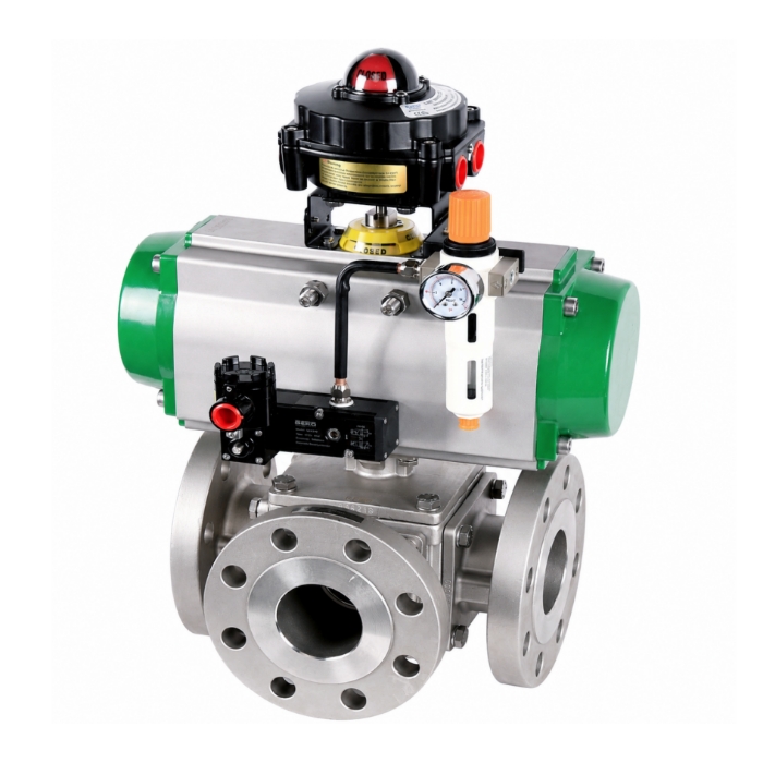
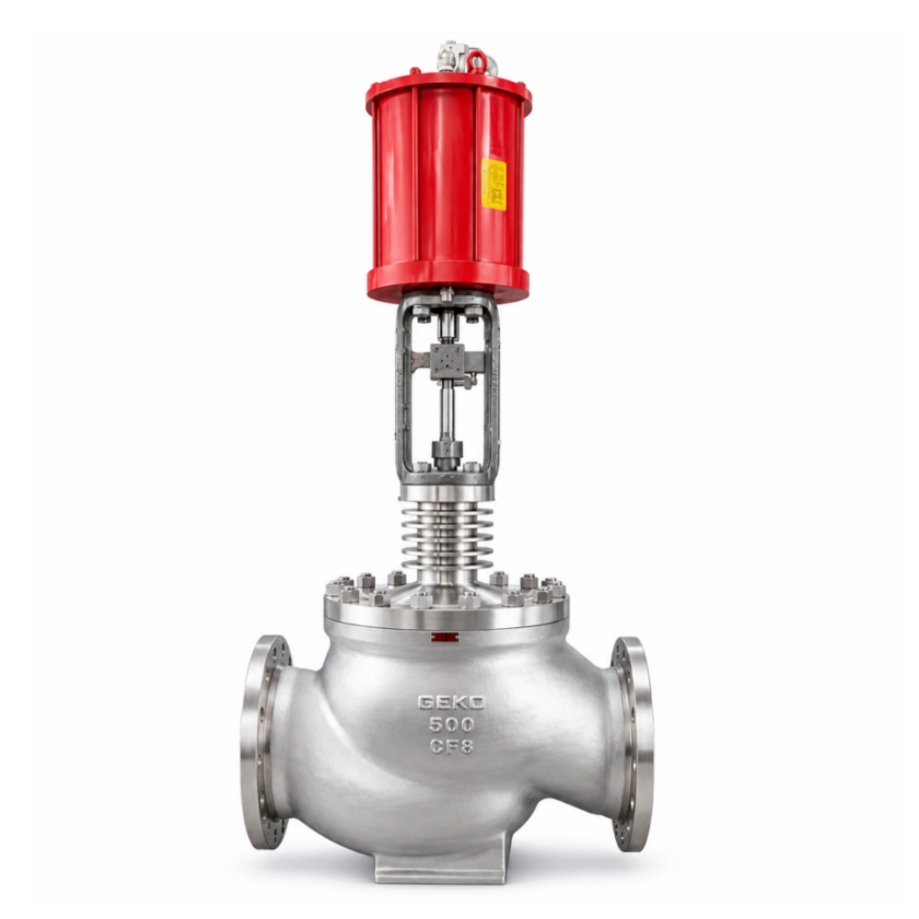
It uses a pneumatically controlled, air-to-close design, consisting of an air supply, cylinder, spring assembly, and solenoid valve. GEKO Valves features an optimized high-temperature spring assembly and low-friction cylinder in this product, ensuring reliable valve opening under air failure conditions, with solenoid valve response time ≤0.5 seconds, significantly improving the timeliness of windage overheating protection.     (ii) BDV Valve (Break Drain Valve — Turbine Emergency Drain Valve) An emergency pressure relief protection valve specifically designed for combined HP-IP turbines, also known as the HP-IP shaft seal residual steam dump valve. Its core function is to quickly discharge steam that leaks past shaft seals under unit load rejection or trip conditions, eliminating the risk of turbine overspeed.     During load rejection or emergency trip of combined HP-IP units, residual steam in the HP cylinder and HP inlet pipes can leak through the HP-IP shaft seal gaps into the IP and low-pressure (LP) cylinders, creating additional driving force on the rotor. If seal teeth are worn or gaps increase, the amount of leaking steam increases, significantly raising the risk of overspeed. The BDV valve directs this residual shaft seal steam directly into the condenser, quickly releasing pressure and completely blocking the overspeed path.   
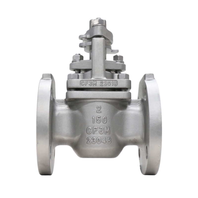
It uses an electromagnetic-pneumatic linkage structure, controlled by the stroke signal of the IP control valve oil servo. GEKO Valves' BDV product adopts a redundant dual-solenoid valve design with a highly reliable pneumatic control circuit, achieving full-stroke action within 0.3 seconds after the oil servo stroke signal is triggered, effectively preventing the escalation of overspeed accidents.   (iii) RFV Valve (Reheat Warm-up Valve — HP Cylinder Reverse Warming Valve) A dedicated warm-up control valve for cold starts, used to pre-heat the HP cylinder before cold start, eliminating casing temperature differences, reducing thermal stress, and ensuring the unit meets parameters for rolling.   
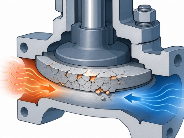
During a cold start, the HP cylinder casing and internal components are at very low temperatures. Directly introducing steam for rolling would create huge thermal stress, leading to casing deformation, metal cracks, and excessive shaft vibration. The RFV valve introduces auxiliary steam upstream of the HP exhaust non-return valve. The steam flows evenly through the HP cylinder and is discharged through HP inner casing drains and HP inlet pipe drains, gradually raising the casing temperature to achieve uniform warm-up.   GEKO Valves has specifically developed an RFV valve with linear regulation characteristics for these operating conditions. It uses a low-leakage seal design and anti-seize valve core, allowing precise temperature control under low flow and low differential pressure conditions, with warming rate control accuracy of ±1.5°C/h, significantly outperforming conventional products.     II. Valve Interlock Control Logic VV Valve Interlock Logic Close Interlock: Receives stroke switch signals from the four HP control valve pre-pilot valves. When all four pre-pilot valves are fully open and unit steam flow reaches 0.5% BMCR, the VV valve automatically closes. 1 minute after unit grid connection, the HP exhaust non-return valve opens, and the VV valve closes via interlock.   Open Interlock: Automatically opens during initial IP start-up and low-load windage conditions. Immediately opens via interlock after turbine trip to quickly evacuate residual HP steam.   BDV Valve Interlock Logic Close Interlock: Controlled by IP control valve oil servo stroke. When oil servo stroke ≥30mm, or when the left/right IP control valve opening reaches 15%~16% (corresponding to ~5% flow command) and the pre-pilot valve is fully open, the BDV valve automatically closes.   Open Interlock: Automatically opens when IP control valve oil servo stroke <30mm. Quickly opens via interlock under turbine trip and load rejection conditions to discharge shaft seal steam.   Pre-Pilot Valve Function Note The turbine control valve pre-pilot valve is an auxiliary valve for the main valve disc. Before the main valve disc opens, the pre-pilot valve opens first, allowing new steam to flow through the pre-pilot passage, balancing the pressure differential across the main valve. This significantly reduces the force required to open the main valve, reduces the oil servo load, and avoids difficult or stuck valve opening.   III. Field Operation & Operational Requirements Pre-Start Check: Before unit start-up and rolling, the open/close status of VV and BDV valves must be confirmed both locally and via DCS. Never start the unit with abnormal valve status.   IP Start-Up Operation: Before start-up, confirm VV and BDV valves are open. If a manual isolation valve is installed upstream of the VV valve, check that it is fully open to avoid false action due to abnormal instrument air pressure or solenoid valve failure.   Post-Valve Transfer: After completing valve transfer following IP start-up, double-check (on DEH screen and locally) that the VV valve is fully closed to prevent steam leakage or pressure abnormalities after HP cylinder admission.   Unstable Conditions: During initial start-up, commissioning, or unstable operation, do not close the manual isolation valve upstream of the VV valve, leaving an emergency path available. After stable operation, close the manual isolation valve promptly.   Post-Trip Emergency: Immediately after a trip during operation, arrange personnel to locally check and open the manual isolation valve upstream of the VV valve, while verifying BDV valve position via DCS and locally, ensuring both valves open correctly for rapid pressure relief.   Normal Start-Stop: Monitor BDV valve position feedback in real-time after the interceptor valve opens during start-up and after a trip to ensure reliable interlock action.   Cold Start Warm-Up: Before rolling during a cold start, open the RFV valve for HP cylinder reverse warming. Monitor drain paths and casing temperature rise rate. Close the RFV valve after warm-up and proceed with normal start-up.   
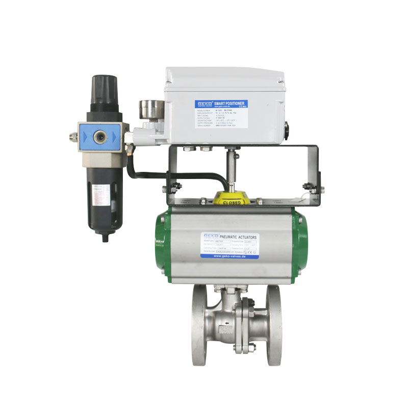
GEKO Valve Note: Accurate valve status feedback is critical in the above operations. GEKO valves come standard with high-precision limit switches and 4-20mA position transmitters, seamlessly integrating with DCS systems to significantly reduce misjudgment risks.     IV. Key Differences & Functions of the Three Valves     Valve Core Function Control Signal Source Main Application VV Valve HP cylinder venting, addresses windage overheating, auxiliary pressure relief after trip HP control valve pre-pilot stroke, steam flow, trip signal Initial IP start-up, low-load operation, turbine trip BDV Valve Discharges shaft seal steam, core overspeed prevention IP control valve oil servo stroke, IP valve opening signal Load rejection, emergency trip, IP valve not fully open RFV Valve HP cylinder cold pre-warming, reduces thermal stress Manual control + warm-up sequence Before turbine cold start     Key Functional Distinction:   VV Valve: Focuses on daily windage overheating protection; auxiliary pressure relief after trip.   BDV Valve: Core overspeed protection valve, specifically targeting shaft seal steam leakage.   RFV Valve: Only used for cold start warm-up, no accident protection function. These three functions are not interchangeable.   GEKO Valves has developed dedicated valve series for each of these three needs, with differentiated designs from material selection (e.g., high-temperature alloy seat for VV valve), sealing structure (metal hard seal + flexible graphite for BDV valve), to actuator configuration (smart positioner optional for RFV valve), ensuring the right valve for each application.   V. Shaft Seal & Stem Leakage System Summary (Typical Plant Configuration) Main Stop Valve: 1st stage leakage → sealing steam header, 2nd stage leakage → sealing steam return header   HP Control Valve: 1st stage leakage → reheater, 2nd stage leakage → sealing steam header   IP Interceptor Valve: Only 1st stage leakage → sealing steam header   BDV Valve: 1st stage leakage → reheater, 2nd stage leakage → sealing steam header   VV Valve: 1st stage leakage → 4th extraction pipe, 2nd stage leakage → sealing steam header   HP Shaft Seal: 3rd stage leakage → 4th extraction pipe   In the above system, GEKO Valves provides matching shaft seal leak control valves and stop valves, ensuring stable leak-off pressures, reducing steam waste, and improving unit thermal economy.   VI. Core Technical Q&A 1. What are the core functions of the VV valve and BDV valve? VV Valve: During IP start-up and low-load operation, connects the HP cylinder to condenser vacuum, evacuating air from the cylinder to reduce windage heating and avoid HP blade/casing overheating. After a trip, quickly releases residual HP steam, assisting in overspeed prevention.   BDV Valve: During a trip or load rejection, quickly discharges steam that leaks from the high-pressure side through shaft seal gaps into the IP cylinder, directly cutting off additional driving force. It is a critical overspeed prevention valve.   2. Why choose GEKO valves for these critical applications? GEKO Valves has over 20 years of experience in developing specialized valves for steam turbines. Our products hold ISO 15848-1 fugitive emission certification and SIL2 functional safety certification. The VV, BDV, and RFV series have accumulated over 100,000 hours of safe operation in multiple ultra-supercritical and subcritical units worldwide, with an action success rate exceeding 99.96%. GEKO provides full-cycle technical support — from valve selection and interlock logic optimization to field commissioning — helping power plants reduce unplanned outage risks caused by valve misoperation or failure to operate.     Conclusion VV, BDV, and RFV valves each play a distinct, non-interchangeable role in turbine start-up and protection. Operating and maintenance personnel must not only master their working principles and interlock logic but also pay attention to the quality and reliability of the valves themselves. GEKO Valves, with solid technical expertise and extensive field experience, provides high-performance, high-reliability products and complete solutions for these three valve types, helping power plants achieve safer and more efficient operation.   For specific valve selection and interlock settings, please refer to the OEM design drawings and actual site conditions. GEKO Valves offers tailored technical consultation.
    阅读更多
  • Geko Fluid Control Technology (Changzhou) Wins Valve Supply Bid from CSSC No.703 Research Institute
    Geko Fluid Control Technology (Changzhou) Wins Valve Supply Bid from CSSC No.703 Research Institute
    Jun 08, 2026
    Geko Fluid Control Technology (Changzhou) Co., Ltd. has successfully won a competitive bidding project from the No.703 Research Institute of China State Shipbuilding Corporation Limited (CSSC). The bid award was officially announced on May 7, 2026, under project number TPJG202605070010.     The scope of supply includes ball valves, butterfly valves, globe valves, and check valves – marking an important milestone for Geko in the marine and ocean engineering sector.   German Engineering, Deep Roots in China   Geko Fluid Control Technology (Changzhou) is the core Chinese subsidiary of GEKO, a well-known European control valve manufacturer with over 60 years of history. GEKO is recognized for high-pressure and extreme-temperature resistance, with some products rated up to 60,000 psi and temperature ranges from -252°C to 649°C.     Founded in 2008 with a registered capital of 50.1 million RMB, the Chinese company is headquartered in Changzhou, Jiangsu Province. Its new factory, launched in 2022, has an annual production capacity of 120,000 units, manufacturing pneumatic/electric ball valves, butterfly valves, control valves, gate valves, globe valves, check valves, actuators, positioners, and limit switches.   Proven Track Record: National Flagship Projects     With robust product quality, Geko has participated in multiple prestigious national projects:   High-speed rail: Custom valves for CRRC high-speed train sets, passing 300,000 km road tests. Ultra-high voltage (UHV) grids: Electric explosion-proof ball valves with a 40-year design life for State Grid. Aerospace & nuclear power: Supply to rocket launch bases, Pakistan nuclear power projects, and multiple Belt and Road international projects. Domestic nuclear power: Products applied in major nuclear projects including the “Linglong One” small modular reactor. Strategic Focus: Hydrogen & New Energy   GEKO’s global strategic priority is the hydrogen energy sector, covering the entire value chain of production, storage, transport, and refueling. Core technologies include anti-hydrogen embrittlement materials, low fugitive emissions, fire and electrostatic discharge protection, and high-pressure (including liquid hydrogen) handling. Applications span hydrogen metallurgy, hydrogen power generation, hydrogen refueling stations, and fuel cell vessels/vehicles.   Leadership Perspective: Hugo Huang   Hugo Huang (Huang Wanzheng), General Manager of Geko Fluid Control Technology (Changzhou), has led GEKO’s China market expansion since 2005. He commented: *"Winning the CSSC No.703 Research Institute project is further recognition of our technical strength and delivery capability. We will continue deepening our presence in marine, nuclear, hydrogen, UHV, aerospace, and other high-end industrial valve markets, contributing to the localization of critical equipment for national strategic projects."*
    阅读更多
  • Geko Valve & Control Makes Early Moves in Pumped Storage Power Stations – A Promising Five Years Ahead
    Geko Valve & Control Makes Early Moves in Pumped Storage Power Stations – A Promising Five Years Ahead
    Jun 08, 2026
    As the global energy structure accelerates toward renewables, pumped storage power stations have become the most mature and economically viable large-scale energy storage solution. In response, Geko Valve & Control, a German manufacturer of industrial valves and control systems, has made early moves in the pumped storage power station sector – with a strong focus on electric ball valves for hydropower plants.     Founded in 1956 (with roots tracing back to 1946), Geko entered the Chinese market in 2005 and established a production base and sales center in Changzhou. The company has already demonstrated its reliability in critical hydropower applications, supplying valves for China's national flagship project – the Baihetan Hydropower Plant.   Tailored Solution for Pumped Storage: GKQ0350-GKV225 DN150 PN25     For pumped storage applications requiring frequent start-stop cycles, high differential pressure, bidirectional flow, and ultra-low fugitive emissions, Geko introduces the GKQ0350-GKV225 electric ball valve – featuring DN150 nominal diameter and PN25 pressure rating. This model is specifically engineered to meet the stringent demands of pumped storage power stations.   Key technologies include HVOF spraying (rocket spray process, hardness up to HRC 66–72) for superior erosion and corrosion resistance, backed by TÜV ISO15848 low-leakage certification and ISO 10497 fire safety compliance.   Looking Ahead   Geko expects strong growth over the next five years as China's 14th Five-Year Plan and subsequent initiatives roll out dozens of new pumped storage projects. The company will continue to advance its valve and control technologies for pumped storage power station systems, contributing to the next-generation power grid.   Beyond hydropower, Geko also serves high-precision and demanding industries including hydrogen energy, LNG, green methanol, nuclear power (e.g., the "Linglong One" mini-reactor), semiconductors, aerospace, and biopharmaceuticals – reinforcing its position as a forward-looking industrial valve specialist.
    阅读更多
  • From 550°C to 1100°C: How to Choose High-Temperature Valve Materials? – A Technical Insight from GEKO Valves
    Jun 03, 2026
    In high-temperature service conditions, the maximum allowable operating temperature of valve materials is one of the key parameters determining operational safety, stability, and service life. Due to differences in composition and microstructure, different materials have significantly different temperature limits. As a professional manufacturer of high-temperature valves, GEKO Valves, drawing on years of engineering experience, provides a systematic analysis of the three most widely used high-temperature valve material families – chrome-molybdenum steel, stainless steel, and nickel-based alloys – to help users make scientific selections based on actual operating conditions and avoid safety hazards such as seal failure and structural deformation caused by exceeding temperature limits.     Chrome-Molybdenum Steel – The Mainstream Choice for Medium-to-High Temperatures   By adding chromium and molybdenum to carbon steel, chrome-molybdenum steel significantly improves creep resistance and oxidation resistance, solving the problems of graphitization and strength degradation commonly seen in ordinary carbon steel at high temperatures. The GEKO chrome-molybdenum steel valve series covers the following common grades:   15CrMoG (equivalent to ASTM A217 WC5): Long-term temperature limit of approximately 540–550°C, suitable for auxiliary steam lines in power plants. WC9: Temperature resistance up to 593°C, widely used in main steam lines of subcritical units in thermal power plants. 2.25Cr-1Mo: Conventional design temperature rating of approximately 565–590°C, and up to 650°C with special stress-relieved treatment. It can reliably serve in medium-to-high temperature environments such as hydrogenation units. GEKO Valves applies optimized heat treatment processes to this material to further enhance high-temperature stability.     Stainless Steel – Combining Corrosion Resistance and High-Temperature Performance   Austenitic stainless steels are widely used due to their good corrosion resistance and high-temperature stability. The GEKO stainless steel high-temperature valve series offers multiple grade options:   304 / 304H: Type 304 is generally recommended for long-term use not exceeding 550°C; for higher temperatures, 304H can be selected. Suitable for high-temperature fluid control without strong corrosion. 316L: Long-term temperature resistance of approximately 550–560°C, suitable for high-temperature corrosive media containing sulfur. 321: Contains titanium, offering excellent resistance to intergranular corrosion, with a long-term temperature resistance of up to 650°C, ideal for high-temperature wet steam systems. GEKO 321 series valves have been successfully applied in multiple steam pipeline projects. 310S: Due to its high chromium and nickel content, it exhibits excellent oxidation and creep resistance, with a long-term temperature resistance of up to 700°C (in oxidizing atmospheres). Commonly used in heat treatment furnaces, incinerator exhaust systems, and other high-temperature applications. GEKO 310S valves provide reliable performance in high-temperature oxidizing environments.   Nickel-Based Alloys – The Core Material for Ultra-High Temperatures   Nickel-based alloys, relying on the excellent high-temperature stability of nickel combined with strengthening effects of chromium, molybdenum, niobium, and other elements, offer significantly higher temperature limits than chrome-molybdenum steels and stainless steels. The GEKO nickel-based alloy valve series covers the following high-end grades:   Inconel 625: Long-term continuous operating temperature of approximately 650–700°C, with short-term peaks up to 815°C. Suitable for petrochemical cracking furnace outlets, high-temperature gas systems, and similar applications. Inconel 718: Long-term temperature resistance of 650–700°C, and up to 980°C for short periods (≤1 hour), combining high-temperature strength and corrosion resistance. Haynes 282 and other high-end grades: Long-term temperature resistance covering 650–950°C. Directional solidification processes further enhance creep strength, making them suitable for extreme high-temperature applications such as nuclear power and concentrated solar power. GEKO Valves can provide customized solutions in these high-end materials. Hastelloy C-276: Long-term temperature resistance recommended within 540–590°C, with strong resistance to highly corrosive acids, suitable for medium-to-high temperature acidic fluid conditions.   Additional Sizing Considerations: Beyond Body Material – GEKO's Complete High-Temperature Sealing Solution   It is important to note that the temperature limit of a high-temperature valve is not the only criterion for selection. The corrosiveness of the medium, operating pressure, and the temperature resistance of sealing materials and seating surfaces must also be considered.   Sealing material: Flexible graphite packing has a recommended long-term temperature limit of 450–500°C in air, and up to 1600°C in inert atmospheres, making it the first choice for high-temperature sealing. GEKO high-temperature valves are standardly equipped with high-quality flexible graphite packing to ensure reliable sealing under high-temperature conditions. Seating surface material: Cobalt-based alloys (such as Stellite 6) welded on sealing surfaces can withstand temperatures above 850°C, improving erosion and wear resistance. GEKO Valves offers Stellite alloy hardfacing options based on specific service requirements. GEKO Valves Recommendation: In practice, the body material, sealing material, and seating surface hardfacing should be matched according to the temperature grade of the operating condition, forming a complete high-temperature resistance system. GEKO Valves provides a complete high-temperature solution, from material selection and sealing pairing to complete valve assembly, ensuring reliable long-term operation of your equipment in the range of 550°C to 1100°C.   Contact the GEKO Valves technical team for high-temperature valve selection advice tailored to your specific operating conditions.  
    阅读更多
  • What's the Difference Between O-Port and V-Port Ball Valves? – Insights from GEKO Valves
    What's the Difference Between O-Port and V-Port Ball Valves? – Insights from GEKO Valves
    Jun 02, 2026
    In industrial fluid control systems, O-port ball valves and V-port ball valves are two common types with different design focuses. Based on years of engineering experience, GEKO Valves provides a detailed comparison in terms of structural design, flow characteristics, regulating performance, shut-off capability, and more, to help you make the right choice.     1. Structural Design   O-port ball valve: The ball has a circular through-hole in the center. When fully open, the hole diameter is basically the same as the pipeline inner diameter, forming a straight flow path. GEKO O-port ball valves are precision-machined for low flow resistance and high sealing performance. V-port ball valve: The ball features a V-shaped notch. GEKO V-port ball valves allow customization of V-notch angle and size according to media characteristics, improving shearing and regulating capabilities.     2. Flow Characteristics   O-port ball valve: Approximate quick-opening characteristic. Flow increases sharply at small openings (e.g., 0°–15°), and reaches 80%–90% of full flow at around 20°–30°. Suitable for fast on/off service, poor throttling capability. V-port ball valve: Approximate equal-percentage characteristic. Flow increases smoothly and linearly with opening, designed for precise throttling. GEKO V-port ball valves maintain excellent controllability even at small openings.     3. Throttling Performance   O-port ball valve: Poor throttling performance. Flow changes drastically at small openings, making precise control difficult; prone to cavitation, vibration, and noise at medium openings. Recommended only for on/off (two-position) control. V-port ball valve: Excellent throttling performance. The V-notch provides stable, predictable flow control, and the V-shaped edge offers shearing action, making it ideal for fibrous, particulate, or slurry media. GEKO V-port ball valves deliver reliable and stable throttling performance.   4. Shut-Off Capability   O-port ball valve: Excellent shut-off capability. With soft or metal seats, it can achieve bubble-tight zero leakage. GEKO O-port ball valves are widely used in applications requiring strict shut-off. V-port ball valve: Relatively weaker shut-off capability. Theoretically, it cannot achieve the same zero-leakage performance as an O-port valve of the same size. Designed primarily for throttling, not absolute shut-off.   5. Flow Resistance   O-port ball valve: Very low flow resistance when fully open, close to a straight pipe, resulting in minimal pressure drop. GEKO O-port ball valves feature optimized flow paths for even lower energy consumption. V-port ball valve: The V-notch creates some flow resistance even when fully open, resulting in a higher pressure drop than an O-port valve.   6. Erosion & Wear Resistance (for media containing solid particles)   O-port ball valve: When switching in particulate-laden media, particles can become trapped between the ball and seat, leading to scoring, wear, or even seizure. V-port ball valve: The sharp edge of the V-notch shears fibers and solid particles, preventing clogging. Better suited for dirty media such as high-viscosity, crystallizing, particulate-laden, or slurry applications. GEKO V-port ball valves excel in wastewater, pulp, slurry, and similar tough services.   7. Typical Applications   O-port ball valve: Suitable for clean liquids and gases (e.g., water, steam, oil, natural gas). The first choice for fast and reliable shut-off. V-port ball valve: Suitable for applications requiring precise flow throttling, especially for challenging media such as pulp, wastewater, slurry, high-viscosity fluids, and crystallizing or scaling liquids. GEKO V-port ball valves are a reliable choice for control valve applications.   8. Cost   Generally, V-port ball valves are more expensive than O-port ball valves of the same size and material due to the more complex machining of the V-notch. GEKO Valves offers various configuration options to balance performance and cost – contact us for sizing recommendations.     9.How to Choose? – GEKO Valve Selection Guide     Requirement Recommended Type Reliable shut-off, zero leakage GEKO O-port ball valve Precise flow throttling GEKO V-port ball valve Clean media Either (depending on functional needs) Media containing particles, fibers, viscous or scaling substances Prioritize GEKO V-port ball valve Budget-limited and on/off only GEKO O-port ball valve   One-sentence summary: O-port ball valves are shut-off experts (tight shut-off), while V-port ball valves are throttling experts (precise control,不怕脏 – not afraid of dirty media). Your choice depends on whether you need shut-off or throttling, and the characteristics of your media.   Why Choose GEKO Valves?   German engineering standards and strict quality control Full range of O-port and V-port ball valves Customizable V-notch design for demanding applications Professional team offering free sizing and selection advice Fast delivery and comprehensive after-sales support 📞 Contact GEKO Valves today for a solution tailored to your operating conditions.  
    阅读更多
  • GEKO Metal Bellows Sealed Globe Valve
    GEKO Metal Bellows Sealed Globe Valve
    May 24, 2026
    GEKO: A Dedicated Valve Brand for Highly Corrosive and Highly Toxic Chemical Media   GEKO is positioned as a specialized valve brand for chemical applications involving highly corrosive and extremely toxic media. Its core product is the metal bellows sealed globe valve, designed for zero fugitive emissions, zero external leakage, and long service life. It is an ideal valve solution for highly toxic media such as chlorine, phosgene, hydrogen fluoride, and other hazardous gases.   Compared with conventional packed globe valves, GEKO bellows sealed globe valves reduce fugitive emissions by more than 100 times and offer a service life 5 to 10 times longer. Compared with other bellows valve designs, GEKO valves feature a more compact structure, easier maintenance, and lower overall operating costs.     Product Series and Technical Parameters   Main Product Series: Bellows Sealed Globe Valves T-Type Straight-Through Globe Valve This is the standard design, covering sizes from DN15 to DN600, pressure ratings from PN16 to PN160 or Class 150 to Class 2500, and operating temperatures from -20°C to +450°C. Y-Type Globe Valve The Y-pattern design offers lower flow resistance and is suitable for high-viscosity media and fluids containing particles. Angle Type Globe Valve With a 90-degree flow path, the angle type globe valve saves installation space and is commonly used for small-diameter, high-pressure applications. Chlorine Service Valve GEKO chlorine valves are designed specifically for dry and wet chlorine service. They meet European chlorine industry standards and are among the products certified by only a limited number of qualified manufacturers. These valves provide excellent corrosion resistance and zero external leakage for chlorine applications.   Materials and Pressure Ratings Valve Body: WCB carbon steel, CF8M stainless steel 316, Alloy 20, Hastelloy C for highly corrosive applications. Bellows: Multi-layer stainless steel bellows, such as 316L or 321, with a fatigue life of no less than 10,000 opening and closing cycles. Disc and Seat: Stellite 6 hardfacing, hardness HRC40–50, providing excellent wear resistance and erosion resistance.   Core Structure and Sealing Principle    Integral Structure: Three-Piece Design, Bellows Seal, No Packing Valve Body The valve body is forged or cast in accordance with ASME B16.34 and can be supplied with flanged or butt-weld ends. Bellows Assembly The multi-layer welded stainless steel bellows is connected to the valve stem at one end and to the valve body at the other end. This structure completely isolates the process medium from the atmosphere, eliminating the need for traditional packing and preventing external leakage. Valve Stem The two-section rising stem design provides reliable sealing performance. The stem is Stellite-coated, anti-rotation, and designed for low-friction operation. Disc and Seat The conical metal-to-metal sealing structure ensures tight shut-off and zero internal leakage. During opening and closing, the sealing surfaces are self-cleaned to maintain reliable sealing performance. Bonnet Flange   The bonnet flange adopts a tongue-and-groove design with a flexible graphite gasket, providing fire-safe performance in accordance with API 607.   Patented Sealing Mechanism for Zero External Leakage Absolute Isolation by Bellows The process medium is sealed inside the bellows, achieving zero fugitive emissions in compliance with TA-Luft requirements. Since there is no packing wear, the risk of external leakage is eliminated. Elastic Preload Compensation The bellows provides inherent elasticity, allowing automatic compensation for thermal expansion, contraction, and wear. This ensures stable sealing pressure during long-term operation. Conical Hard Sealing The disc and seat are precision-lapped to a micron-level finish. When closed, the metal sealing surfaces fit tightly together, achieving zero internal leakage in accordance with API 598. Anti-Torque Design   The bellows is equipped with an anti-rotation limiting structure to prevent torsional fatigue during valve operation, significantly extending service life.     Application Conditions and Performance Limits   Recommended Applications   GEKO bellows sealed globe valves are especially suitable for the following severe service conditions: Media: dry and wet chlorine, phosgene, hydrogen fluoride, hydrogen chloride, toxic gases, high-temperature steam, hot alkali, and high-temperature media containing particles. Temperature Range: -50°C to +450°C; special alloy designs can reach up to 550°C. The valve maintains stable performance under alternating hot and cold conditions. Pressure Range: Class 150 to Class 2500, or PN16 to PN160, with reliable high-pressure sealing and no internal leakage. Industries: chlor-alkali chemical plants, coal chemical industry, petroleum refining, fertilizer production, fine chemicals, and pharmaceutical manufacturing.   Applications Not Recommended Strongly abrasive media with large particles, such as high-slag black water. In such cases, a hard-seated ball valve is recommended. Low-pressure, large-diameter applications, where soft-seated butterfly valves may offer better cost performance. Very frequent opening and closing operations, because bellows have a limited fatigue life. For high-cycle services, wear-resistant ball valves are recommended.   Maintenance Guidelines and Common Faults   Key Maintenance Principles for Toxic and High-Temperature Services Never disassemble under pressure. The bellows is a thin-wall component and may rupture if disassembled under pressure. The valve must be fully depressurized to 0 MPa before maintenance. Protect the bellows from impact. The bellows has a multi-layer thin-wall structure. Hammering, squeezing, scratching, or impact damage is strictly prohibited. Soft tools should be used during disassembly and assembly. Keep maintenance records.   All maintenance steps, including disassembly, cleaning, inspection, replacement, assembly, and pressure testing, should be recorded with written notes and photos for traceability.   Common Faults and Solutions Internal Leakage or Poor Shut-Off Possible causes include coking on the sealing surface or particles stuck between the disc and seat. The valve should be disassembled, cleaned, and lapped. If the disc or seat is worn, the sealing components should be replaced. If the bellows is fatigued, the bellows assembly must be replaced. Sticking or High Operating Torque This may be caused by ash accumulation in the valve cavity, bellows deformation, or stem corrosion. The valve should be disassembled and cleaned. Deformed bellows must be replaced, and corroded stems should be derusted and lubricated with high-temperature grease. Bellows Leakage, Rare Case Possible causes include fatigue at the welded area or corrosion by the medium. The bellows should be replaced, and the material should be upgraded when necessary, such as using Hastelloy C for highly corrosive media.   Selection and Procurement Recommendations Operating Conditions First For highly toxic, highly corrosive, high-temperature, and high-pressure applications, GEKO bellows sealed globe valves are the preferred choice. For media containing particles, GEKO hard-seated ball valves are recommended. Size and Pressure Selection DN15 to DN200 and Class 300 to Class 600 are the most commonly selected and cost-effective ranges. Spare Parts Strategy   It is recommended to keep spare bellows assemblies, disc and seat sets, and bonnet gaskets of the same specifications in stock. This helps reduce maintenance downtime and overall repair costs.   Contact us for more: info@geko-union.com  
    阅读更多
  • GEKO耐腐蚀旋转阀、旋塞阀和三偏心蝶阀
    GEKO耐腐蚀旋转阀、旋塞阀和三偏心蝶阀
    May 20, 2026
     品牌定位和背景GEKO阀门· 创立于:1956年,德国· 专业领域:耐腐蚀、高可靠性旋转阀核心目标:零泄漏、低排放、高安全性产品范围:旋塞阀、高性能蝶阀、氟衬阀· 典型行业:化工、炼油、烷基化、酸碱、浆料、精细化学品主要优势:自动擦拭、无需润滑、可在线维修、防火安全  重点产品系列a) 旋塞阀(套筒阀)套筒式无润滑旋塞阀结构:锥形塞+PFA/PTFE套管,自清洁特点:零泄漏、无需润滑、可调节且可在线维修密封:PFA/PTFE套管,双向应用领域:强酸、强碱、化学加工、烷基化装置维护:无需研磨即可更换套筒  全衬里PFA旋塞阀结构:全PFA内衬主体和插头应用领域:极端腐蚀、卤素、氧化剂、高纯度环境特点:金属完全隔离,零腐蚀,无沉积物。  高性能旋塞阀结构:PFA封装锥形座温度范围:-40°C 至 274°C优点:耐磨性高、使用寿命长、维护简便 b) 高性能蝶阀三偏心金属密封蝶阀结构:三偏心金属层压密封压力等级:150/300/600 级,PN16–PN100密封性:符合 ISO 5208 A 级零泄漏标准,符合 API 607 防火标准应用领域:高温、石油天然气、蒸汽、气体、工艺回路特点:运行顺畅,闭合更紧密,使用寿命长 双偏心蝶阀应用范围:中高压、双向密封、低扭矩优点:可替代闸阀/截止阀,结构紧凑,重量轻氟内衬蝶阀全PFA/PTFE内衬,耐腐蚀  核心技术套管密封:PFA/PTFE套管,自清洁,零泄漏,在线可调反向唇形阀杆密封件:PFA反向唇形密封件+弹簧预紧,动态和静态双重密封,符合ISO 15848低排放标准防火设计:通过 API 607 认证,高温下密封性能良好在线维护:无需拆卸阀门即可更换套筒、密封件或轴承。 材料和密封件 成分常用材料应用程序身体WCB、CF8M、Alloy20、哈氏合金普通腐蚀性、强腐蚀性插头/光盘316、Alloy20、PFA涂层耐腐蚀和耐磨损主密封PFA、PTFE、TFE、金属层压板耐化学腐蚀、耐高温、防火阀杆密封PFA 反唇,石墨低排放,防火安全衬垫PFA、PTFE、FEP极度腐蚀  典型应用及型号酸/碱化学品 → 旋塞阀极端腐蚀/氟要求 → 全衬里 PFA 旋塞阀精炼/烷基化 → 专用旋塞阀耐高温气体,防火安全,零泄漏 → 三偏心蝶阀泥浆、废水、颗粒物 → 氟衬蝶阀  GEKO阀门维护流程1.拆卸:拆下执行器→盖板→塞子/碟片→套筒/密封件2.更换零件(全面检修):PFA/PTFE套筒、阀杆密封件、轴承、O型圈、执行器维护3.组装:对准塞子/碟片,均匀预紧密封件,遵循扭矩标准,平稳完成全行程操作4.压力测试:本体压力为标称压力的1.5倍,密封件压力为标称压力的1.1倍,保持时间≥5分钟,无泄漏,需提供测试证书。  GEKO 阀门与标准阀门  特征GEKO标准阀海豹自清洁套管,零泄漏易磨损,内部泄漏维护在线可维修,无需润滑需要拆卸寿命长度延长 3–5 倍短的排放低排放认证标准耐腐蚀性超高标准 概括重点关注套筒、密封件和对准情况旋塞阀:更换阀套和密封件,对齐阀芯蝶阀:三偏心设计,注重密封,同心设计,注重衬里。所有阀门:经过两次压力测试,并颁发证书极端腐蚀:请使用正品 PFA/PTFE,不可使用替代品。 GEKO 专注于耐腐蚀旋转阀,主要产品为旋塞阀和三偏心蝶阀,具有零泄漏、自清洁、可在线维修和低排放等特点,是化工、炼油、酸碱作业的理想之选。维护重点在于更换阀套/密封件、精确对准和严格的压力测试。 更多信息请联系我们:info@geko-union.com 
    阅读更多
  • 阀门内部再次泄漏?GEKO揭示阀门密封表面损坏的六大主要原因
    阀门内部再次泄漏?GEKO揭示阀门密封表面损坏的六大主要原因
    Apr 29, 2026
    在石油化工、发电、冶金和制药等工业系统中,阀门内部泄漏是一个常见问题,会影响系统的安全、效率和运行稳定性。内部泄漏的主要原因之一是阀门密封表面的损坏。作为专注于工业阀门和流量控制解决方案的品牌,GEKO 凭借多年的应用经验,总结了阀门密封表面失效的六个常见原因,帮助用户更准确地识别问题,优化阀门选择,延长使用寿命。  1.侵蚀损害当介质中含有固体颗粒(例如催化剂粉末、铁锈或沙粒)或高速气液两相流通过阀门时,密封表面会受到持续的高频冲击。这会导致局部区域出现沟槽、点蚀或线状磨损。这种情况在节流工况下尤为常见,此时流速显著增加,高速流体可能会将密封表面“吹”出径向流痕。典型的迹象是沿介质流动方向出现明显的线性侵蚀。 GEKO 提醒:对于含有颗粒物、流速高或具有腐蚀性的介质,应优先考虑具有更强抗腐蚀性的密封材料和结构设计。  2.接触应力引起的塑性变形和压痕阀门关闭瞬间,密封表面承受极高的接触压力。如果材料硬度不足或关闭力过大,密封表面可能会发生塑性变形。软质材料容易出现表面凹陷,而硬质材料则可能发生局部剥落。经过长时间反复的开合,密封表面的表层可能会逐渐发生“加工硬化”,从而产生微裂纹,最终发展为分层失效。 GEKO 建议:对于高频运行或高压差应用,应注意密封件的硬度匹配和闭合力的控制,以避免因过载而导致密封表面过早失效。  3. 高温下的蠕变和软化在蒸汽或导热油系统等高温管道中,阀门密封表面材料可能会发生两种类型的有害变化。一方面,高温会软化材料,降低其硬度,削弱其抗刮擦和耐磨性能。另一方面,在持续压力下,密封表面可能发生蠕变变形,破坏其精确的密封轮廓。此外,高温会加速氧化皮的形成。一旦氧化层脱落并进入密封副,就会进一步加剧摩擦和磨损。 GEKO温馨提示:对于高温应用,阀门选择应重点关注材料的高温强度、抗氧化性和密封稳定性。 4. 电化学腐蚀和缝隙腐蚀当密封件采用不同的金属材料时,例如不锈钢阀座与司太立合金硬面密封面结合,在电解质介质中可能会形成原电池,从而导致电化学腐蚀。更重要的是,阀门关闭后,密封表面之间可能会形成微小缝隙。介质可能滞留在这些缝隙内,造成氧浓度差异,从而导致局部腐蚀、深坑或腐蚀孔。如果存在氯离子,不锈钢密封表面还可能发生应力腐蚀开裂。 GEKO 建议:对于腐蚀性介质,应综合评估介质成分、温度、浓度和材料相容性,以选择更合适的防腐密封解决方案。  5. 热冲击引起的开裂和剥落频繁快速开启和关闭的阀门,例如程序控制阀和安全阀,其密封表面经常会受到反复的热冲击。由于表面温度变化速度快于基材,因此会产生循环热应力。当应力超过材料的疲劳极限时,表面会逐渐出现网状热疲劳裂纹。随着裂纹不断扩展并相互连接,可能会发生局部剥落,形成“龟裂”或“龟壳状”破坏模式。 GEKO温馨提示:对于温度波动较大、操作频繁的应用场合,应选择耐热疲劳性能较好的阀门密封材料和结构。 6. 密封表面间介质滞留引起的加速腐蚀当阀门长时间保持部分开启、轻微泄漏或密封不良的状态时,高压侧介质会不断冲刷密封表面,而腐蚀性介质可能会在低压侧停滞。在停滞区域,pH值、离子浓度和腐蚀产物的积累变化会显著加速局部腐蚀。腐蚀速率甚至可能比正常流动条件下高出数倍,最终形成可迅速穿透密封表面的局部蚀坑。 GEKO建议:阀门运行过程中,应避免长时间部分开启节流或在存在泄漏的情况下运行。定期检查密封性能并及时处理轻微的内部泄漏,可防止小问题演变成严重故障。 GEKO结论阀门密封表面损伤很少是由单一因素造成的。大多数情况下,它是侵蚀、磨损、腐蚀、高温、热冲击和运行条件等多种因素共同作用的结果。选择合适的阀门不仅仅需要考虑压力等级和尺寸。介质特性、温度范围、工作频率、压差和腐蚀风险等因素都应进行全面评估。 GEKO致力于为工业用户提供可靠、高效且针对特定应用场景的阀门解决方案,帮助客户降低内部泄漏风险,提升系统安全性和运行稳定性。欢迎联系我们了解更多信息!
    阅读更多
  • 阀门的Cv值是多少?
    阀门的Cv值是多少?
    Apr 24, 2026
    阀门的流量系数(Cv 值)本质上是一个用于量化阀门流量的核心指标。该概念最初在美国提出,其标准定义如下:当阀门完全打开,阀门两端的压差为 1 psi(磅/平方英寸),温度为 60°F(约 15.6°C)时,Cv 值表示每分钟流过阀门的净水量(以美制加仑为单位)。虽然这个定义看似复杂,但其核心目的是建立统一的测试标准,使不同类型和尺寸的阀门能够在相同的“参考条件”下进行直接比较。这为工程选型提供了标准化的基础。 在实际工程应用中,Cv 值通常使用简化的公式计算:Cv = Q × √(SG / ΔP)在哪里:Q 是介质的流速(单位为加仑/分钟,GPM),SG 是介质的比重(以水为参考,水的比重为 1),ΔP 是阀门两端的压力差(单位为 psi)。 从该公式可以看出,在恒定压差条件下,Cv 值越大,阀门的流量越大。反之,已知 Cv 值和流量,即可精确计算阀门的压降,从而有助于系统压降控制。该公式适用于所有类型的液体介质。对于气体介质,必须考虑压缩性和温度效应等因素,并在应用该公式前进行相应的修正。 Cv 与 Kv 值 在工程实践中,许多技术人员会将 Cv 值与 Kv 值(国际公制等效值)混淆。这两个值的核心功能相同,但测试标准和单位有所不同。Kv 值定义为:当阀门两端的压差为 1 bar,温度介于 5°C 和 40°C 之间时,每小时流过阀门的净水立方米数。Cv 和 Kv 之间的转换关系很简单:Cv ≈ 1.17 × Kv 或 Kv ≈ 0.86 × Cv 例如,Cv 值为 100 的阀门,其 Kv 值约为 86。了解这种换算关系有助于工程师使用来自不同国家和标准的技术文档,避免因单位差异而导致的选择错误。 阀门选择的最佳 Cv 值 需要强调的是,在选择阀门时,并非Cv值越高越好。Cv值的选择应结合阀门的调节特性。阀门的理想调节范围为10%至80%的开度。在此范围内,阀门具有良好的线性度和较高的控制精度。如果选择的Cv值过大,阀门将长时间保持小开度状态,此时即使是微小的流量变化也可能导致压力剧烈波动,从而造成控制不稳定。另一方面,如果Cv值过小,即使阀门完全打开,也可能无法满足系统的最大流量需求,从而在管道中形成“瓶颈”,影响系统的整体效率。 正确的选型方法是先计算系统最大流量所需的最小Cv值,然后预留20%~30%的裕量,并确保阀门在正常运行条件下开度在40%~70%的最佳范围内。这种平衡既能保证良好的调节精度,又能保证流量效率。 并联阀和串联阀的 Cv 值计算 另一个常见的误解涉及并联或串联阀门的 Cv 值计算。对于并联阀门,总 Cv 值就是各阀门 Cv 值之和。然而,对于串联阀门,总 Cv 值并非简单的相加。由于串联配置中存在累积压差,两个具有相同 Cv 值的阀门串联后,其总 Cv 值仅为单个阀门 Cv 值的 0.707 倍。这一特性在旁通设计和双阀截止应用中尤为重要,因为计算误差可能导致系统流量控制问题。 实际应用中的CV测量 在实际应用中,测得的 Cv 值可能与阀门铭牌上的标称值有所不同。实验室测试通常使用洁净的冷水进行,而实际工业环境往往涉及高温蒸汽、粘稠油或其他难处理介质,导致 Cv 值与标称值出现偏差。对于粘性流体,必须使用雷诺数修正系数对 Cv 值进行修正。对于气体和蒸汽等可压缩流体,如果压差超过入口压力的 50%,则可能发生阻塞或空化现象,导致流量不再随压差增加。在这种情况下,直接使用基本公式而不进行修正会导致计算误差,并影响选型精度。 CV值随时间变化及设备维护 从维护角度来看,阀门的实际流量系数(Cv值)会随时间推移而变化,这受到管道内水垢积聚、内部部件磨损以及密封件老化等因素的影响。这会导致阀门流量下降。一些运行多年的阀门,其实际流量系数可能低至标称值的80%。因此,对于关键应用(例如安全联锁或精确介质混合),定期检查阀门流量并解决任何流量下降问题至关重要,以确保系统稳定运行。 如果没有阀门的 Cv 曲线,可以根据阀门的类型近似计算 Cv 与开度的关系: 闸阀、球阀和旋塞阀通常具有快速开启的特性。球阀通常具有线性或近似线性特性,控制阀(如截止阀和蝶阀)的特性可以是等百分比的,也可以是线性的,这取决于阀芯的设计。 结论 总而言之,了解 Cv 值对于平衡系统中的流量、压降和阀门开度至关重要。Cv 值过大可能导致控制不稳定,而 Cv 值过小则可能造成流量瓶颈。通过精确匹配 Cv 值与系统需求,可以优化能源效率和系统稳定性。当我们查看阀门铭牌上的 Cv 值时,它不再仅仅是一个冰冷的技术参数——它是理解流体系统性能并确保整个系统平稳运行的关键。
    阅读更多
  • 为什么GEKO的三偏心蝶阀能够重新定义超低温蝶阀的密封标准?
    为什么GEKO的三偏心蝶阀能够重新定义超低温蝶阀的密封标准?
    Apr 22, 2026
    在当今工业领域,阀门在低温条件下的密封性能至关重要,尤其是在气体输送、石油化工和化学等行业,低温设备的稳定运行依赖于高质量的阀门密封件。GEKO的三偏心蝶阀凭借其独特的设计和先进的技术,重新定义了低温蝶阀的密封标准,确保了卓越的密封性能和安全性。  为什么选择GEKO三偏心蝶阀? 纯金属密封结构,真正防火设计GEKO的三偏心蝶阀采用纯金属密封结构,不仅能承受极端温度,还能有效防止火灾隐患。无论在极低温还是极高温环境下,GEKO阀门都能提供无与伦比的安全性能,确保长期稳定运行。    双向零泄漏等级 A,低温下为 BS6364 标准的三分之一GEKO的密封技术确保双向零泄漏,即使在极寒环境下也能显著降低泄漏量。此外,其泄漏率低至BS6364标准的三分之一,极大地提升了阀门的环境和经济效益,帮助企业减少资源浪费。  密封件对,硬化表面 STL12/STL6,在各种工况下均具有耐久性GEKO阀门采用STL12/STL6材料硬化表面,即使在严苛的工作条件下也能提供卓越的耐久性和高耐磨性。这确保了密封件即使在苛刻的环境下也能长期保持优异的密封性能。 双倒角密封面,密封角度针对特定工况设计GEKO的三偏心蝶阀采用双倒角密封面,密封角度根据具体工况设计,确保周向密封压力的均匀性。这种创新设计有效解决了低温条件下阀门卡滞的问题,提高了流体控制的精度和稳定性。  弹性密封件对设计,确保双向密封,低扭矩,长寿命GEKO阀门的弹性密封件设计确保双向密封过程中扭矩低,从而显著延长阀门的使用寿命。这种设计在低温环境中尤为重要,因为频繁的操作可以减少维护频率并提高运行效率。  一体式阀杆确保扭矩传递和阀杆刚性,防止变形。GEKO的三偏心蝶阀采用一体式阀杆设计,确保稳定的扭矩传递和阀杆刚性,防止变形影响密封性能。阀杆刚性保证了阀门在长期运行中的可靠性,即使在低温环境下也能保持稳定运行。  阀杆与阀板之间采用全键连接,确保连接强度并防止卡滞。GEKO的三偏心蝶阀采用阀杆与阀板之间的全键连接,确保连接牢固,防止卡滞。即使在极低温度条件下长时间使用,这种设计也能保证阀门平稳运行。 重型司太立合金焊接支撑轴承,可承受高压和双向载荷GEKO 的阀门配备了重型司太立焊接支撑轴承,能够承受高压和双向载荷,确保阀门在高压或双向流动条件下保持优异的密封性能和结构稳定性。  独特的三重防爆设计,确保现场本质安全GEKO的三偏心蝶阀采用独特的三重防爆设计,有效防止密封失效或阀门损坏导致气体泄漏,保障现场操作人员的安全。该设计体现了GEKO对产品安全的承诺,确保设备本质安全。  GEKO三偏心蝶阀优势概述GEKO的三偏心蝶阀凭借其先进的设计理念和高性能密封技术,彻底颠覆了低温蝶阀的标准。GEKO三偏心蝶阀采用纯金属密封结构、双向零泄漏、弹性密封副设计等创新技术,在确保卓越密封性能的同时,显著提升了设备的耐用性和安全性。无论是在高压、低温还是其他极端工况下,GEKO三偏心蝶阀都能提供可靠的密封解决方案,是严苛环境的理想之选。 更多信息请联系我们:info@geko-union.com
    阅读更多
  • 升杆式闸阀和非升杆式闸阀的区别
    Apr 14, 2026
    升杆式闸阀和非升杆式闸阀是工业应用中最常用的两种闸阀类型。二者的核心区别在于阀杆的运动方式,这种结构上的差异也体现在防护性能、安装要求、维护难度以及适用场景等方面。本文将从核心特性到实际应用,详细阐述这两种闸阀的区别,帮助用户在选择合适的阀门时快速区分它们。 1. 结构和茎运动差异升杆式闸阀的核心特点是阀杆与闸板同步上下运动。阀杆上的螺纹直接暴露在阀体外部。阀门开启时,闸板上升,阀杆伸出阀体顶部。阀门关闭时,闸板下降,阀杆缩回阀体内部。通过观察阀杆伸出的长度,即可直接判断阀门的开启程度。 另一方面,非升降式闸阀的阀杆仅旋转,不随闸板上下移动。阀杆上的螺纹隐藏在阀体内部,与闸板上的螺纹啮合。阀杆的旋转带动闸板上下移动,从而实现阀门的开启或关闭。从外部看,阀杆长度固定不变,无法直接观察其开启和关闭过程。2. 性能和使用特点 阀门状态指示升杆式闸阀能够直观地显示其开启状态。通过观察阀杆的伸出或缩回,即可轻松确定阀门的开启程度,这使其在需要清晰观察阀门状态的场合尤为实用,例如消防系统、泵站和其他关键基础设施。这使得操作人员能够快速评估阀门的状况。相比之下,非升降杆式闸阀无法直接观察其状态,因为阀杆不会垂直移动。其状态必须通过阀门指示器或操作人员的操作手感来推断。如果指示器缺失或不清晰,则操作失误的风险会增加,使操作过程更容易出错。防护性能升杆式闸阀的阀杆螺纹暴露在外部环境中,更容易受到灰尘、湿气和腐蚀性气体等外部因素的影响。随着时间的推移,螺纹可能会生锈、卡死或受到外力损坏。因此,升杆式闸阀的防护能力相对较弱,更适合室内或洁净环境。相比之下,非升降杆闸阀的螺纹完全隐藏在阀体内部,从而免受灰尘和腐蚀性物质的侵蚀。其防护性能更优,使其成为室外、地下或介质具有腐蚀性或含有杂质的恶劣环境的理想选择。安装空间要求升杆式闸阀需要阀体上方留有足够的空间,以便阀杆在运行过程中上下移动。如果空间不足,可能会影响阀门的正常开启和关闭。因此,这类阀门不适合安装在空间受限的地方,例如天花板下方或狭窄的设备缝隙中。另一方面,非升降杆闸阀只需要阀杆旋转运动,不需要垂直运动空间。这使得它们结构更紧凑,更适合安装在狭小空间内,例如地下管道、船舶机舱或管道密集的管道系统。维护难度和成本升杆式闸阀的外露螺纹易于维护。定期清洁和润滑可防止卡死和生锈,维修无需拆卸整个阀门。维护成本更低,维护效率更高。对于非升降杆闸阀,螺纹隐藏在阀体内部,因此不拆卸阀门就难以进行日常维护。如果螺纹卡死或生锈,则必须完全拆卸阀门才能进行维修。这增加了维护的难度、时间和成本。 适用的媒体和应用升杆式闸阀最适用于水、油和天然气等洁净介质,因为外露的螺纹不易堵塞或腐蚀。常见应用包括水厂、泵站、消防系统、石油化工行业的洁净管道以及高层建筑的给排水系统。  GEKO 控制阀集成在考虑像GEKO控制阀这样的高性能阀门解决方案时,值得注意的是,它们在密封、控制和维护方面都具有显著优势。GEKO控制阀可以与升降杆式和非升降杆式闸阀无缝集成,尤其适用于对流量控制要求极高的工业应用场景。例如,GEKO阀门能够根据实时数据进行自动调节,从而提升升降杆式闸阀的运行性能,确保阀门即使在环境挑战下也能保持最佳工作状态。对于非升降杆式阀门,GEKO 控制阀在保持紧凑设计的同时,进一步提升了控制性能。这使其成为空间有限但对阀门可靠高效运行要求极高的应用的理想之选。 凭借GEKO先进的控制系统,两种阀门类型均可受益于预测性维护,从而减少停机时间并提高系统整体效率。GEKO在阀门技术领域的专业知识确保其控制系统在洁净和严苛的运行环境中均能提供卓越的性能,为任何管道或流体控制系统增添显著价值。 
    阅读更多
  • 火力发电蒸汽减压阀的阶梯式降压模型研究
    火力发电蒸汽减压阀的阶梯式降压模型研究
    Apr 14, 2026
    近期,浙江大学特种控制阀研究团队对火电厂蒸汽减压阀关键调节部件的热工水力特性进行了系统研究。相关研究成果以论文《基于降阶模型的火电厂蒸汽减压阀热工水力特性快速预测》的形式发表于《国际传热传质通讯》(中国科学院第二区顶级期刊)。针对传统CFD数值模拟和实验研究方法在效率和成本方面的局限性,本文构建了一种基于特征正交分解(POD)的降阶模型(ROM),实现了复杂流场的快速重构和高效预测,在保证工程精度的前提下,显著提高了计算效率。 蒸汽减压阀是火力发电厂的关键调节部件。由于计算成本高、耗时长,分析其复杂的热工水力特性十分困难。为解决这一问题,本研究采用特征正交分解(POD)方法建立了一个降阶模型(ROM)。首先,对不同出口压力和行程下的流场进行数值模拟;其次,利用POD方法提取空间模态和模态系数;最后,通过克里金模型、支持向量机回归和基于物理的支持向量回归等拟合方法,建立了模态系数与工况之间的关系。 结果表明,与CFD模拟相比,降阶模型(ROM)的计算效率提高了四个数量级以上。ROM结果的最大误差为13.59%。ROM能够预测压力、温度和熵的分布,相对均方根误差(RRMSE)小于2%。本文提出了一种新的降阶模型框架,用于预测减压阀内部物理量的分布。 此外,本研究为开发流体动力学应用中工程部件的快速、准确的预测模型提供了参考。  研究背景 蒸汽减压阀是火电厂蒸汽系统中的关键调节部件。它负责将高温高压过热蒸汽(约2 MPa,574℃)的压力降低到下游所需压力,并通过调节开度来控制流量。随着削峰需求的日益增长,阀门需要频繁操作。如果阀门内部出现堵塞(Ma≥1),可能会导致效率下降甚至设备损坏。因此,实时监测内部流场对于安全运行至关重要。然而,阀门内部处于极高的温度和压力环境中,难以在节流孔等关键位置安装传感器,难以掌握真实的内部压力、流速和温度分布。目前,蒸汽减压阀的研究主要依赖于实验和CFD模拟,但在效率和成本方面存在明显的不足。因此,本文构建了一种基于特征正交分解(POD)的降阶模型(ROM)。其核心思想是:从少量高精度CFD计算结果中提取主要流动模态并重构流场。随后,建立工况参数与模态系数之间的简单映射关系。在新工况下,无需重新求解复杂的流体力学方程,即可快速重构完整的流场。 研究方法 构建降阶模型的基础是建立高质量的训练样本库。本研究选取了四个出口压力(1.2 MPa、1.4 MPa、1.6 MPa、1.8 MPa)和六个阀门行程(20 mm 至 120 mm),并将它们组合成 24 组稳态计算工况,涵盖了该蒸汽减压阀的典型工况范围。  经火电厂现场数据验证,CFD 计算流量与测量值之间的最大偏差为 9.70%,满足工程精度要求,保证了后续 ROM 输入数据的可靠性。  采用特征正交分解(POD)方法来降低CFD快照数据的维度。将每组流场物理量(密度、压力、速度、温度、马赫数、熵)排列成行向量,构建快照矩阵X(m×n维,其中m=24为样本数,n≈8×10⁶为网格节点数)。 POD:X ≈ UΣVβ 是通过奇异值分解 (SVD) 实现的。其中,U 包含模态系数信息,V 包含空间模态信息,Σ 的对角元素为奇异值,代表每个模态的能量贡献。按能量降序排列后,第一模态贡献了压力场能量的 85.72% 和熵场能量的 88.00%。前 12 个模态的累积能量达到 99%,因此选择截断阶数 k=12,并舍弃高阶模态以滤除数值噪声。  为了预测新的工况,需要建立工况参数(出口压力p、阀门行程h)与模态系数α之间的映射关系,即α=f(p, h)。本研究比较了三种回归方法:多项式回归、克里金法和支持向量回归。此外,该研究尝试了物理信息支持向量机回归。将动量方程的残差项引入SVR损失函数,并采用梯度下降算法优化超参数ε,使得预测的流场满足对称平面上稳态NS方程的动量守恒约束。然而,结果表明,由于POD基函数是从满足控制方程的CFD快照中提取的,因此该基函数本身包含了足够的物理信息;在样本有限的情况下,基本的SVR已接近该表示框架的精度上限。引入物理约束作为次要优化项并没有显著降低预测误差(RRMSE 1.16% vs 0.87%),反而可能由于约束过多而导致局部区域偏差增大。   最终降阶模型(ROM)的在线预测过程如下:输入目标工况参数(p,h),通过克里金模型插值获得12个模态系数α,并将预先存储的空间模态在u(X)=Σα dvϕ和dv(X)处进行线性叠加,以重构完整的流场分布。该过程的计算复杂度为O(k×n)。在配备AMD EPYC 7763的计算平台上,单次预测耗时约4.8秒,比CFD的11665秒高出四个数量级。 研究结果 以压力预测结果为例,基于克里金模型的降阶模型对对称平面压力场的预测结果表明,相对均方根误差(RRMSE)为0.79%,最大相对误差为16.49%;基于支持向量机回归(SVR)模型的RRMSE为0.87%,最大相对误差为15.38%。两种方法均能将压力分布的相对误差控制在20%的工程可接受范围内,且RRMSE均小于1%。 值得注意的是,在外套筒和内套筒之间的环形间隙区域,由于流通面积的突然增大,流量下降,压力出现明显的反弹现象,压力值上升至1.53 MPa至1.88 MPa之间。随后,蒸汽流经内套筒的节流孔(二次节流),压力再次下降,最终与下游出口处的压力达到平衡。这种“压力下降-反弹-再次下降”的非单调压力分布特征被ROM模型准确捕捉到。无论是Kriging方法还是SVR方法,它们的预测曲线均与CFD参考值吻合良好,仅在局部梯度最大的区域存在微小偏差。 在阀腔主体区域以及进出口管路区域,压力变化相对平缓,相对误差一般小于5%,部分区域甚至小于1%。最大相对误差为16.49%,出现在外套筒节流孔出口附近壁面的局部位置。此处流动分离较为剧烈,高阶模态中断造成的细节损失最为明显。尽管如此,该误差水平仍处于工程应用中压力趋势判断和整体载荷评估的可接受范围内。 对三种拟合方法在流场预测中的性能进行了比较:Kriging模型的RRMSE精度为0.79%,略优于SVR的0.87%,两者在最大误差水平(约15-16%)上相当。引入物理信息约束的PI-SVR方法在压力预测方面并未展现出优势。其RRMSE为1.16%,最大误差达到17.67%,且与基本SVR相比,节流孔高梯度区域的误差分布范围有所扩大。 这一现象表明,对于压力这类具有强非线性但空间结构相对固定的物理量,基于高斯过程的克里金插值法能够更好地处理小样本和非参数映射关系。因此,对于蒸汽减压阀流场的快速预测,克里金模型被确定为最优解决方案。 研究前景 该研究成果为减压阀的数字孪生构建提供了一条可行的技术路径。该低模态模型能够实现阀门内部压力场和温度场等关键参数的实时重构和可视化监测,解决了传统传感器无法安装在节流部件内部所导致的“黑箱”问题。 然而,需要指出的是,本研究建立的降阶模型具有明显的适用范围。首先,该模型的有效范围严格限定于训练数据所覆盖的参数空间,无法外推至未采样的几何形状或不同的边界条件。其次,当前模型基于稳态快照构建,仅适用于稳态工况的预测,无法捕捉阀门快速动作过程中瞬态流动的演变。 后续研究将从以下两个方面深化和扩展当前的工作: 第一种方法是瞬态流动建模。通过结合时间序列分析方法(例如动态模态分解DMD或长短期记忆网络LSTM),构建了一个能够预测非定常流动演变的动态降阶模型。 第二点是优化物理信息方法。重新审视物理信息机器学习的实现策略,探索在模态提取阶段而非回归阶段引入物理约束,或者采用结合低分辨率CFD和物理信息神经网络的多保真框架,以提高模型在样本稀疏区域的外推能力和物理一致性。   
    阅读更多
1 2 3 4 5 6 7 8
总计 8页面

留言

留言
如果您对我们的产品感兴趣并想了解更多详细信息,请在此处留言,我们会尽快回复您。
提交

主页

产品

接触